
TRIAC Light Dimmer Circuit
The dimmer circuit utilizes a TRIAC (Triode for Alternating Current), a semiconductor device that can control power flow in AC circuits. The basic operation involves phase control, where the TRIAC is triggered at a specific point in the AC waveform. By delaying the triggering point, the effective voltage and current supplied to the load (in this case, incandescent or LED lights) are reduced, resulting in dimming.
The circuit typically includes a few key components: a TRIAC, a diac (if necessary for triggering), a potentiometer for adjusting the dimming level, and various passive components such as resistors and capacitors for stability and filtering. The TRIAC is connected in series with the load, and the gate of the TRIAC is controlled by the phase control mechanism.
When the circuit is powered, the potentiometer adjusts the voltage at the gate of the TRIAC, controlling when it turns on during each AC cycle. As the resistance of the potentiometer is varied, the point at which the TRIAC is triggered changes, allowing for a smooth transition between full brightness and complete dimming.
It is crucial to ensure that the TRIAC selected for this application can handle the load current and voltage. The heat generation is minimal due to the efficient design of the TRIAC, but adequate heat sinking may still be necessary depending on the specific load conditions and ambient temperature.
This circuit is not compatible with fluorescent lights due to their different electrical characteristics and the way they operate. Fluorescent lights require a different type of dimming circuit, typically involving electronic ballasts designed specifically for that purpose.
Overall, this TRIAC-based dimmer circuit is an effective solution for controlling the brightness of incandescent and compatible LED lights, providing a simple and efficient way to enhance lighting environments.This little circuit can be used to dim lights up to about 350 watts. It uses a simple, standard TRIAC circuit that, in my expirience, generates very little heat. Please note that this circuit cannot be used with fluorescent lights. 🔗 External reference
Related Circuits
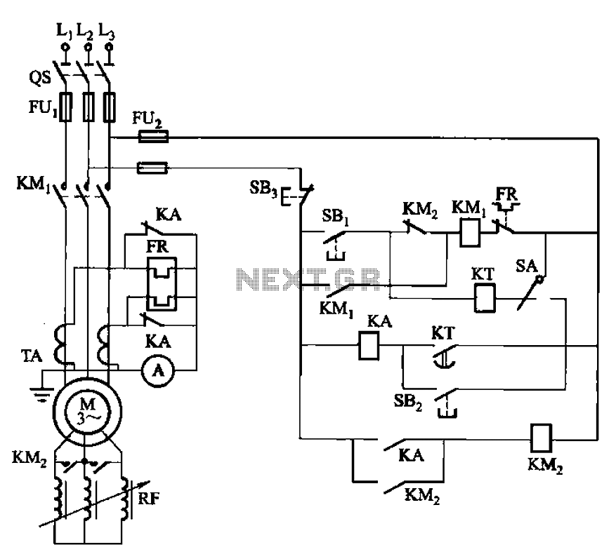
The circuit shown in Figure 3-164 can operate in both manual and automatic modes. During startup, the normally closed contact of relay KA is shorted, which affects the heating element to avoid prolonged startup times that could lead to...
A second RM output and a sync input have been added to the 555 timer circuit. The sync input is derived from one of Rene Schmitz's voltage-controlled oscillators (VCOs). There are two transistors in the PCB images that lack...
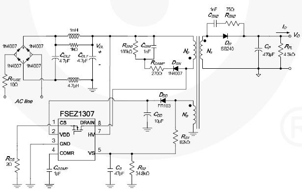
This cell phone charger circuit diagram electronic project is based on the FSEZ1307 third-generation primary side regulation (PSR) PWM controller integrated circuit. The FSEZ1307 cell phone charger can be used for battery charger applications for devices such as cellular...
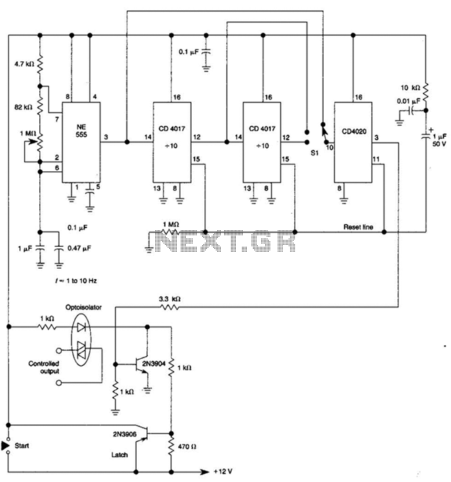
By using three 555 ICs, three sequential pulses can be generated. Output 3 can be connected back to the trigger input to achieve astable operation. The circuit described utilizes three 555 timer integrated circuits (ICs) configured to generate three sequential...
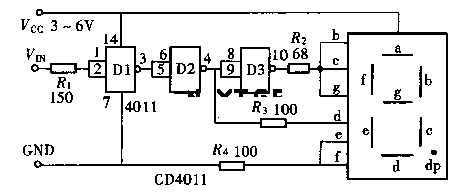
The door circuit logic pen text display can take many forms, utilizing various logic gates such as inverters, NAND gates, NOR gates, and others. A logical pen, exemplified by the NAND gate CD4011, can be used in conjunction with...
The amplifier drives a pair of speakers using two LM3876 amplifier chip circuits (50 watts per channel) or a pair of headphones with Meier Crossfeed through a clarifier and a dual OPA2134 Opamp. It features four selectable band inputs...
Warning: include(partials/cookie-banner.php): Failed to open stream: Permission denied in /var/www/html/nextgr/view-circuit.php on line 713
Warning: include(): Failed opening 'partials/cookie-banner.php' for inclusion (include_path='.:/usr/share/php') in /var/www/html/nextgr/view-circuit.php on line 713