
Triangle-square-wave-generator
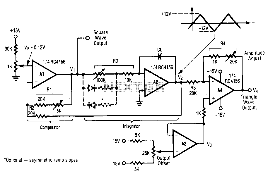
This circuit utilizes a positive-feedback loop that encompasses a combined comparator and integrator. Upon the application of power, the output of the comparator transitions to one of two states, either the maximum positive or maximum negative voltage. This action delivers a peak input signal to the integrator, causing the integrator's output to ramp either down or up, in opposition to the input signal. When the integrator output, which is connected to the comparator input, reaches a threshold defined by resistors R1 and R2, the comparator will switch to the opposite polarity. This cycle continues indefinitely, with the integrator alternately charging positively and negatively, while the comparator operates in a square-wave manner.
This circuit operates based on a feedback mechanism that ensures continuous oscillation between two voltage states. The comparator, often implemented using an operational amplifier (op-amp), compares the voltage levels at its inverting and non-inverting inputs. The output of the comparator will saturate at either the positive or negative supply voltage, depending on the comparison result.
The integrator, which is typically configured with a capacitor and resistor, integrates the output voltage over time. When a peak voltage is applied, the integrator begins to charge or discharge, depending on the polarity of the input signal from the comparator. The time constant of this integration process is determined by the values of the resistor and capacitor used in the integrator circuit.
The resistors R1 and R2 form a voltage divider that sets the threshold voltage at which the comparator switches states. This threshold is critical for determining the frequency of oscillation. By adjusting the values of R1 and R2, the behavior of the circuit can be tuned to achieve desired oscillation characteristics.
As the integrator ramps up or down, it eventually reaches the threshold voltage set by the resistors. At this point, the comparator detects that the threshold has been crossed and switches its output to the opposite state. This action resets the integrator's output, causing it to begin the charging process in the opposite direction. The result is a square wave output from the comparator, which reflects the continuous charging and discharging behavior of the integrator.
In summary, this circuit exemplifies a classic configuration for generating square wave signals through the interplay of a comparator and an integrator, effectively demonstrating the principles of feedback and signal processing in electronic design.This circuit uses a positive-feedback loop closed around~a combined comparator and integrator. When power is applied, the output of the comparator will switch to one of two states, to the maximum positive or maximum negative voltage. This applies a peak input signal to the integrator, and the integrator output will ramp either down or up, opposit" of the input signal.
When the integrator output, which is connected to the comparator input, reaches a threshold sefby R1 and R2, the comparator will switch to the opposite polarity. This cycle will repeat endlessly, the integrator charging positive then negative, and the comparator switching in a square-wave fashion. 🔗 External reference
Related Circuits
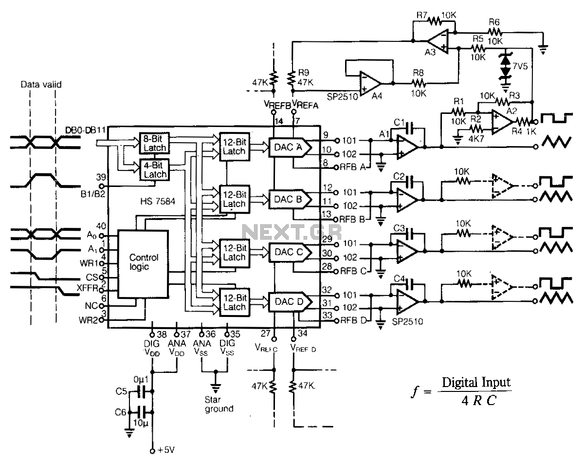
The programmable multiple output generator provides control signals for the data converter automated test equipment (ATE). Major performance criteria include simple interfaces with various microprocessor systems, low power consumption, stable output timing relationships, and minimal board space requirements. For...
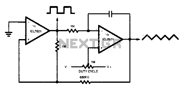
The output range varies precisely from rail to rail, making the frequency and duty cycle nearly independent of power supply variations. The circuit in question is designed to operate with a wide output range that spans from the minimum to...