
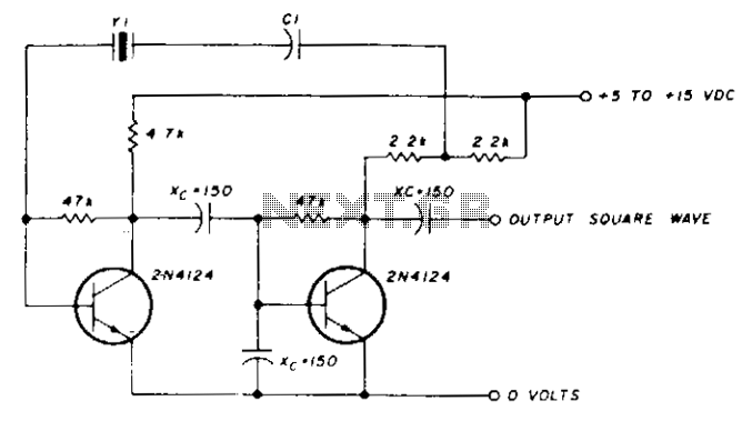
Triangle/Square-Wave Oscillator Serves Dual Purpose

The versatile triangular-wave and square-wave oscillator circuit employs a Schmitt trigger configuration to generate stable and adjustable waveform outputs. The design allows for independent control of the voltage levels and amplitude of the triangular waveform through reference voltages VR1 and VR2, which are adjustable via potentiometers. This capability enhances the circuit's flexibility, making it suitable for various applications where precise waveform characteristics are required.
The frequency of the output waveform can be modified using a variable resistor (R1), which is designed to not interfere with the amplitude settings determined by VR1 and VR2. This separation of frequency and amplitude control is a significant advantage over conventional designs, where changes to one parameter often affect the other.
Additionally, the circuit can utilize external voltage sources for VR1 and VR2, enabling integration with digital systems. When DACs are employed, the circuit transforms into a digitally controlled oscillator, allowing for precise and programmable waveform generation. The linear relationship between the time period of oscillations and the reference voltages provides further versatility, enabling the generation of both triangular and square waveforms with ease.
The output characteristics, as illustrated in the accompanying figure, demonstrate the functionality of the circuit. TR1A displays the triangular waveform, while TR2A shows the square waveform generated at point b of the circuit. The voltage levels set by the potentiometers are represented by TR3A and TR4A, illustrating the adjustable nature of the circuit. This design approach not only simplifies the process of waveform generation but also enhances the potential applications in signal processing, waveform synthesis, and other electronic systems requiring adaptable signal characteristics.In conventional triangular-wave oscillators, hysteresis from positive feedback in the Schmitt trigger determines the voltage levels and amplitude of the triangular waves. With this topology, it`s difficult to independently vary the voltage levels and amplitude of the output waveforms.
To combat this limitation, a more versatile oscillator was designed ( Fig. 1 ). With this circuit, the voltage levels and amplitude of the triangle waves can be precisely and independently varied by changing the reference voltages VR1 and VR2. After setting VR1 and VR2 using two potentiometers, the frequency can be adjusted using the variable resistance R1 without affecting the amplitude of the triangle waves.
The beauty of the circuit lies in the fact that VR1 and VR2 can be fed from any external source and, if DACs are used, a digitally amplitude-controlled triangular-wave oscillator is created. As can be seen from the equation above, the time period of the oscillations can be linearly varied with VR2 or VR1 by keeping R, C, and VZ constant.
Thus, the same circuit also can generate square waves whose period can be varied linearly with VR2 or VR1. The period of the oscillation can be increased by boosting VR2 and keeping VR1 constant, or decreased by increasing VR1 and keeping VR2 constant.
The output of the versatile triangular-wave/square-wave oscillator is shown in Figure 2. Here, TR1A is the triangular waveform seen at point a in Figure 1. TR3A and TR4A are the voltage levels VR2 and VR1 set by two potentiometers. TR2A is the waveform as seen at point b of the circuit. 🔗 External reference
Related Circuits
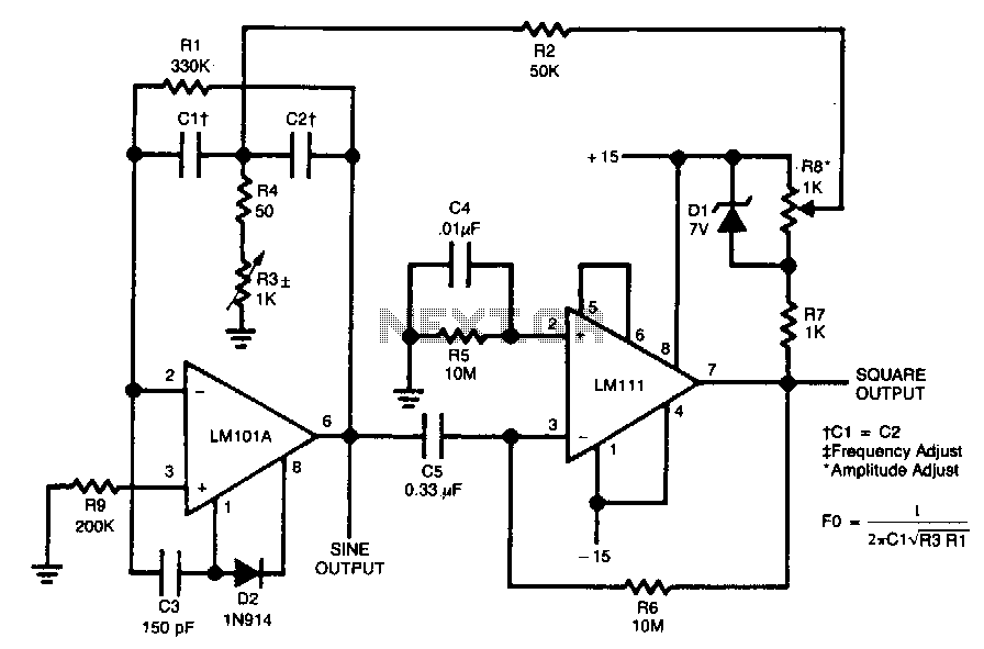
The circuit is designed to generate both sine and square wave outputs for frequencies ranging from below 20 Hz to above 20 kHz. The frequency of oscillation can be easily adjusted by modifying a single resistor, which is a...
A sine wave oscillator can be implemented using a Wien-Bridge oscillator, similar to the previous sine wave oscillator circuit; however, another method is now presented. The Wien-Bridge oscillator is a type of electronic oscillator that generates sine waves. It is...
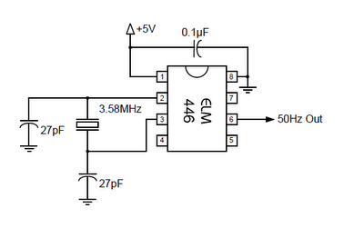
The ELM446 is an 8-pin digital divider integrated circuit that generates both 50Hz and 1Hz outputs from a common 3.58MHz NTSC colorburst crystal. The designer needs to supply only the crystal and two suitable loading capacitors, along with a...
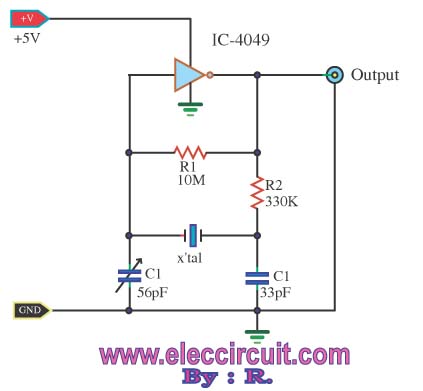
A friend requires a pulse generator oscillator circuit that maintains a stable frequency of 32.768 kHz for a digital CMOS binary counter. The pulse generator oscillator circuit designed to operate at a frequency of 32.768 kHz is commonly used in...
A capacitor in series with the crystal may be utilized to adjust the oscillator output frequency. The value may range between 20 pF and 0.01 µF, or it may be a trimmer capacitor, and it will approximately equal the...
A Crystal Colpitts oscillator can be constructed using a parallel mode crystal and a transistor. The circuit is depicted in the accompanying figure. In this configuration, an inductance is utilized. The Crystal Colpitts oscillator is a type of electronic oscillator...