
Tritium Solar engine
The Tritium circuit, classified as a type 3 solar engine (SE), represents an early experimental design that serves as a prototype for further development. The circuit's primary component is an NPN transistor (Q1), which plays a crucial role in regulating the flow of current through its base-emitter junction. The operation begins with the solar energy being harnessed to charge a capacitor, which is integral to the circuit's function.
In this configuration, the capacitor charges through the base-emitter junction of Q1. During this phase, the transistor remains in a saturated state, allowing current to flow freely. This results in the collector voltage being held low, effectively maintaining a stable state until the capacitor reaches a certain charge threshold. As the charging current diminishes, the transistor transitions from saturation, causing the collector voltage to rise due to the lack of sufficient base current to keep it in the low state.
The design of the Tritium circuit emphasizes its experimental nature, as it has been observed to outperform other existing solar engine designs, such as the Freds. This performance can be attributed to the efficient charging mechanism facilitated by the NPN transistor, which allows for a rapid response to changes in solar input. The prototype nature of the circuit suggests that while it demonstrates promising results, further refinement and optimization are necessary to enhance its reliability and efficiency in various applications.
Overall, the Tritium circuit serves as a significant step in the evolution of solar engine technology, providing insights into the potential for improved designs and applications in renewable energy systems.The Tritium circuit was the first (to my knowledge) type 3 SE. As such, it is quite experimental, and should be regarded as a prototype rather than the `state of the art`! Nevertheless, it does function reasonably well, and in some circumstances outperforms other solar engines such as the Freds that I have lying around.
It works by charging the capacitor through the base-emitter junction of an NPN transistor (Q1). When current is flowing through this junction, the collector is held low. When the charging current tapers off, the collector will start to drift higher pulled 🔗 External reference
Related Circuits
The typical home solar power system primarily comprises a roof-mounted solar panel, a charge controller, and a storage battery bank, along with direct or electric connections. A home solar power system is designed to harness solar energy for residential use,...
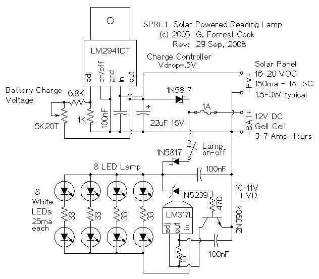
The reading lamp consists of a small solar panel, a standard UPS style lead acid battery, and an LED circuit board. The circuit board contains a low power solar charge controller (regulator), a set of 8 white LEDs, a...
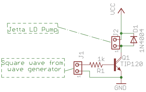
Reverse Engineering an EVAP System - Part 1. A 1997 Volkswagen Jetta (I4) is experiencing issues with the EVAP system, which has been a challenge for numerous mechanics attempting to diagnose the problem. The EVAP (Evaporative Emission Control) system is...
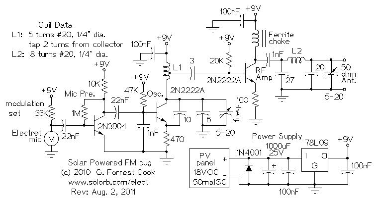
Numerous miniature FM transmitter bug circuits are available online; however, this particular design is distinctive as it operates entirely on solar power, eliminating the need for a battery. The transmitter will function as long as sunlight is incident on...
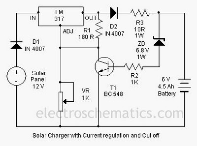
A solar charger circuit is designed to charge lead-acid batteries or nickel-cadmium (Ni-Cd) batteries using solar power. This circuit captures solar energy to charge a 6-volt, 4.5 Ah battery for various applications. It features voltage and current regulation along...
This circuit controls a stepper motor using an L6221A integrated circuit (IC). A power supply from a printer can be utilized to provide the necessary DC voltages. All ground pins on the Centronics connector should be connected to ground....