
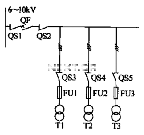
Trunk main wiring system diagram a formula
The installation of a 6-kV bus segment at the circuit breaker is critical for ensuring reliable power distribution within a substation. The decision to incorporate isolating switches, load switches, or isolating contact head groups is contingent upon specific operational scenarios. For instance, manual intervention may become necessary in the event of an accident, necessitating the ability to switch power supplies manually. Additionally, scenarios where load operation is not required or where protection and automatic devices are absent must also be considered when determining the configuration of the bus segment.
The transformer power switch within the substation must be installed with precision, as it plays a vital role in managing the electrical supply. This switch should be complemented by protective devices to ensure safety and reliability. In radial power supply systems, the inclusion of isolating or load switches is essential to facilitate safe maintenance and operation.
In configurations where the transformer high-voltage power distribution room is in close proximity, the installation of a switch may further enhance operational flexibility. The low self tie breaker must adhere to specific operational criteria, including automatic recovery capabilities and the presence of a three-position selector switch, which allows for optimized control of the circuit.
The low-voltage tie breaker should be designed with a cast delay feature, providing a delay of 0 to 1 second to prevent unwanted tripping during transient conditions. Furthermore, in the event of a failure of the low-voltage main circuit breaker, it is imperative that automatic access through the tie breaker is disabled to maintain system integrity.
The interaction between the low-voltage side of the main circuit breaker and the electric interlock tie breaker must be carefully managed to prevent concurrent operation with the network, which could lead to operational conflicts. Additionally, when integrating an emergency power supply, such as a diesel generator, into the low-voltage distribution systems, it is crucial to establish a clear interconnection with the external network. This interconnection must be designed to prevent simultaneous operation, thereby avoiding confusion in power billing and ensuring that critical loads receive uninterrupted power in non-accident scenarios. The wiring configuration should be flexible enough to accommodate the varying needs of important loads while maintaining system stability.6-lOkV bus segment at the circuit breaker should be installed, but when any of the following circumstances, can be equipped with isolating switch or load switch or isolating co ntact head group. 1) when the accident manual switching power supply to meet the requirements; 2) do not need to operate with a load; 3) protection or automatic device No I 4) less outgoing circuit. Substation transformer power switch installed irresolute: as a way to stem Sh supply, shown in Figure 15-8, should be installed with a protective Kaimei set equipment.
In radial power supply should be installed isolating switch or load switch. When the transformer high-voltage power distribution room adjacent paste, may be installed switch. When the low self tie breaker vote manner, shall meet the following requirements: should be installed in automatic recovery, self pitcher Fu, since the vote out three position selector switch status. Low-voltage tie breaker from the cast delay O ~ ls. When the low-voltage main circuit breaker failure guillotine opening, does not allow automatic access through the tie breaker.
The low pressure side of the main circuit breaker and electric interlock tie breaker should not be and network operation. When the emergency power supply (eg diesel generator) access substation low-voltage distribution systems, and power supply should be set between the external network interconnection, network and may not run.
To avoid confusion with the outer A power billing. On the wiring to have a certain. Flexibility to ensure that give some important load power in the non-accident.
Related Circuits
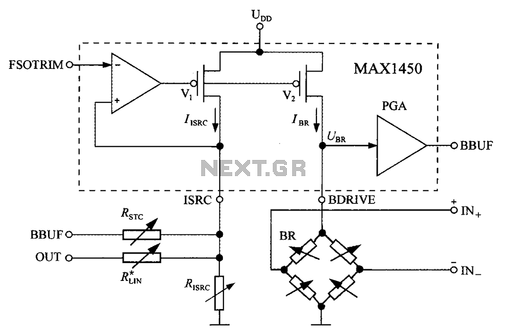
The circuit diagram for the bridge integrated pressure signal conditioner MAX1450 is composed of various components. The MAX1450 is a high-performance integrated circuit designed for signal conditioning in pressure sensing applications. It is particularly suited for use with resistive bridge...
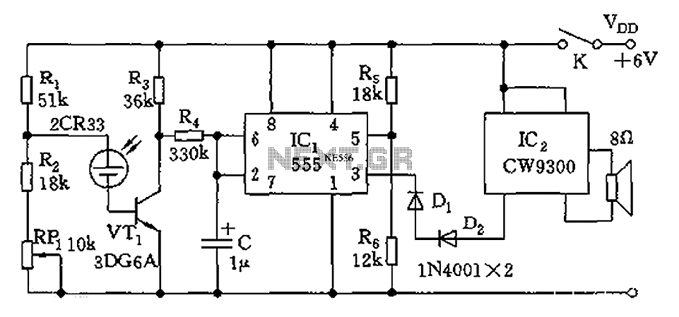
The circuit utilizes photoelectric sensors and a 555 timer to respond to music prompts. The illumination sensor components consist of photovoltaic cells (2CR33). When the light level drops below the optimal learning illumination of 100 lux, the 2CR33 exhibits...
Do not forget to seal your wire splices with heat shrink tubing. It provides tensile strength to wires, is flame-retardant, and protects against fraying. Heat shrink tubing forms a protective, insulated, water-resistant covering over wiring splices, crimp terminals, and...
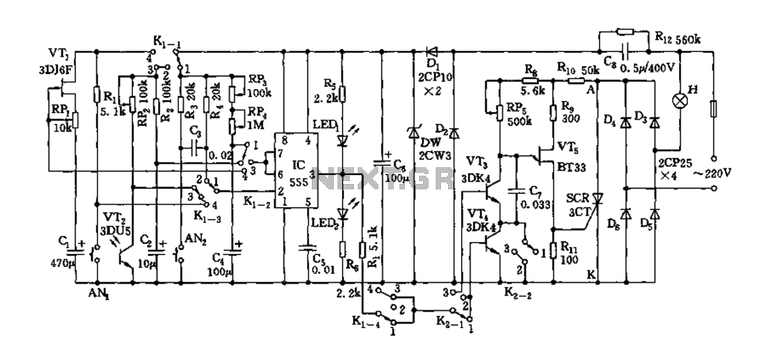
Depending on the external circuit connection, the 555 timer can be configured for various modes such as start delay, trigger delay, multi-harmonic oscillation, and other operational conditions. It functions as a versatile tester with the inclusion of some RC...
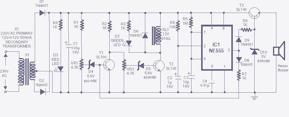
The high and low voltage cut-off with delay and alarm circuit, along with its circuit diagram, is explained in this post. The high and low voltage cut-off circuit is designed to protect electrical devices from damage caused by excessive voltage...
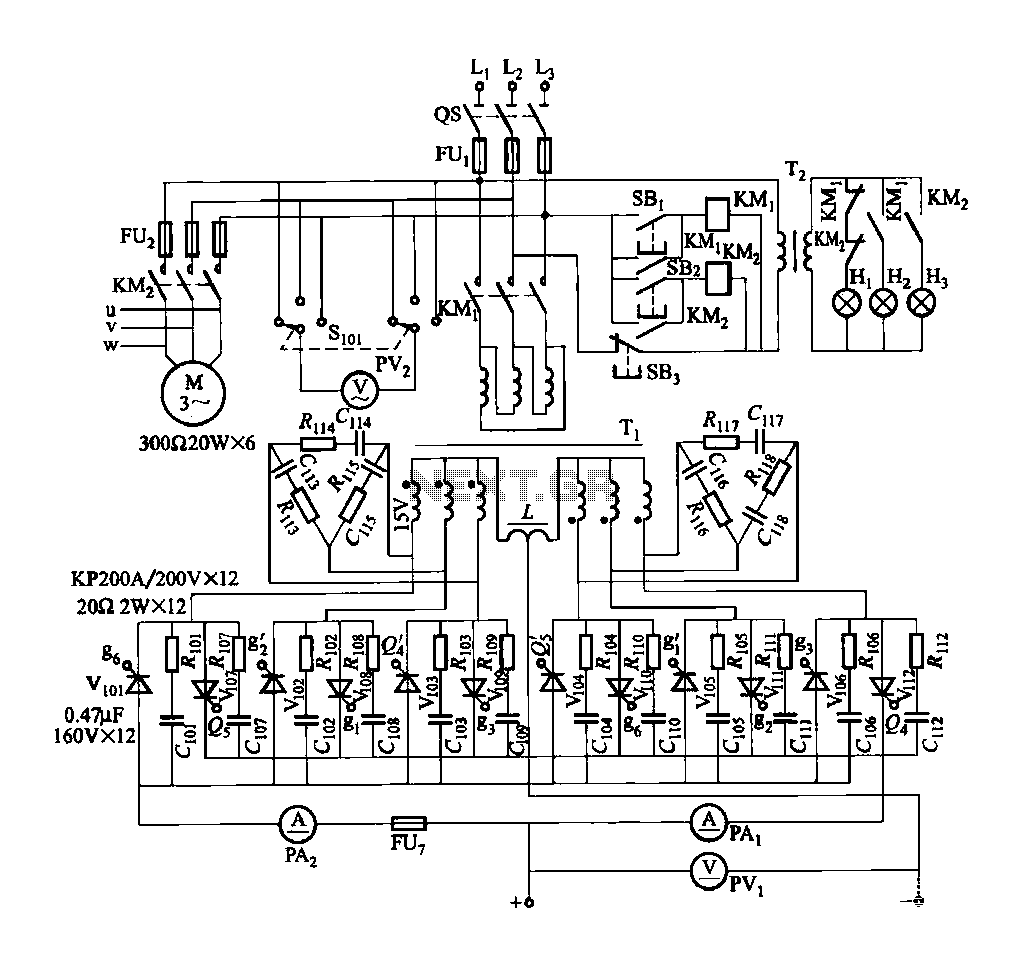
FGDF-3 is a three-phase low-temperature iron plating main circuit, while the KGDF-3 represents a low-temperature iron plating power supply device that includes characteristics of a single-phase low-temperature iron plating power supply. This device utilizes a three-phase power grid to...