
Tutorial on using ADC (Analog to Digital converter) unit of AVR micro controller
The ADC unit in the Atmega8 microcontroller is a crucial component that allows for the conversion of analog signals into digital data, facilitating the processing of real-world signals in embedded systems. The Atmega8 features a 10-bit ADC, which can convert an input voltage range of 0 to Vref (typically 5V) into a digital value ranging from 0 to 1023.
To implement the ADC functionality, the following key components are typically included in the circuit design:
1. **Microcontroller**: The Atmega8 serves as the central processing unit, managing the ADC operation and processing the converted digital values.
2. **Analog Input Source**: This could be any analog sensor or signal generator, such as a potentiometer or temperature sensor, connected to one of the ADC input pins (e.g., ADC0).
3. **Reference Voltage**: The ADC requires a reference voltage (Vref) to determine the scale of the input signal. This can be supplied externally or set to the internal reference of the microcontroller.
4. **Decoupling Capacitors**: It is advisable to place decoupling capacitors close to the power supply pins of the microcontroller to ensure stable operation and reduce noise.
5. **Programming Interface**: The Atmega8 can be programmed using AVR programming tools, with code written in C or assembly language to configure the ADC, initiate conversions, and read the results.
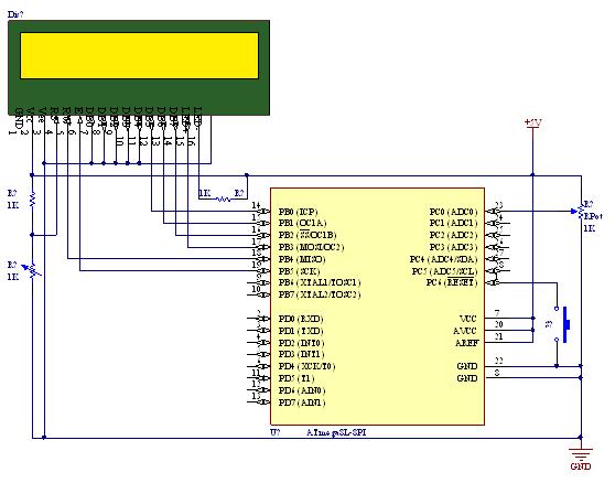
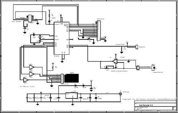
The circuit diagram typically illustrates the connection of the analog signal to the ADC input pin, the power supply connections, and any necessary pull-up or pull-down resistors. The code example would include initializing the ADC, selecting the appropriate channel, starting the conversion, and reading the ADC value.
In summary, the tutorial provides a comprehensive guide to using the ADC unit of the Atmega8 microcontroller, covering both hardware setup and software implementation, making it an essential resource for engineers and hobbyists working with analog signal processing in embedded systems.A simple tutorial on using ADC (Analog to Digital converter) unit of AVR micro controller illustrated using Atmega8 with circuit diagram & codes.. 🔗 External reference
Related Circuits
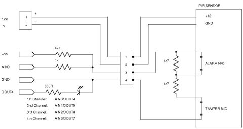
Security system sensors such as motion detectors, reed switches, pressure mats, glass-break detectors, infrared beams, and conductive film can be very useful for various applications, including home automation systems, interactive art installations, and security systems. Almost all security system...

This is the design circuit diagram of an ultrasonic mosquito repeller. The circuit operates based on the theory that insects, such as mosquitoes, can be repelled by sound frequencies in the ultrasonic range (above 20 kHz). The circuit utilizes...
This preamplifier amplifies the signal from a microphone, an amplifier so that it can be further strengthened. The circuit supplies an output signal line. With two transistors, it is not difficult to build such a circuit. The amplifier produces...
Well, it's pretty much a PAiA preamp - usual input circuitry followed by one half of dual op-amp rigged in fixed 20dB amplification circuitry, followed by second stage which is adjustable for up to 40dB amplification, for up to...
This is a three-stage discrete amplifier with gain control. Alternative transistors such as BC109C, BC548, BC549, and BC549C may be used with minimal impact on performance. The first stage, built around Q1, operates in a common base configuration. While...
A device for measuring daily insolation has been developed. The device is constructed using a PIC18F458 microcontroller and a 128MB Multimedia Memory Card (MMC). The insolation measurement device leverages the capabilities of the PIC18F458 microcontroller, which is known for...
Warning: include(partials/cookie-banner.php): Failed to open stream: Permission denied in /var/www/html/nextgr/view-circuit.php on line 713
Warning: include(): Failed opening 'partials/cookie-banner.php' for inclusion (include_path='.:/usr/share/php') in /var/www/html/nextgr/view-circuit.php on line 713