
TV Transmitter Audio and video IC LM1889
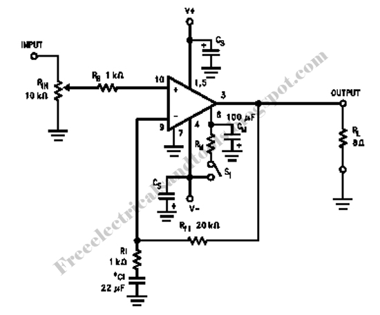
The circuit includes all necessary stages for processing audio and video signals for television transmission. Coil L1, in conjunction with a parallel capacitor, generates a 4.5 MHz signal that modulates the audio, separating it from the video carrier frequency. The adjustment of this coil is straightforward, requiring tuning to 4.5 MHz to ensure proper audio output. Audio modulation is achieved through a varicap, allowing for simple intensity adjustments of the audio signal sourced from the output of the sound table, ensuring quality reproduction.
The video signal, obtained from the output of any camera, video cassette, or DVD player, is applied to pin 13 of the integrated circuit following an amplification stage involving two transistors. The oscillator frequency must be adjusted to match a free VHF channel, typically in the lower range (channels 2 to 6) where the broadcasting station will operate. The RF output, available at pin 11, is sent to an amplification stage with a transistor, which then connects to an antenna, such as a dipole or telescopic antenna for short-range transmissions.
It is important to note that the audio modulation in this circuit generates two subcarriers, one below and one above the 4.5 MHz frequency of the channel. If not adequately filtered, one of these subcarriers may cause interference with adjacent channels. Therefore, selecting a free channel without adjacent active channels is crucial. The power supply for the circuit can utilize either 12 volts (7812) or 15 volts (7815) from a source capable of delivering at least 1A with excellent filtering. Poor filtering may result in noise in the audio and ripples in the video signal. Resistors used should be rated at 1/8W or higher. The power supply can be sourced from a standard 12V/1A adapter, or modifications can be made to operate with 15V by changing the transformer and the integrated circuit. The printed circuit board layout for assembly is illustrated below, with coils being critical components of the design. L1 is constructed from 40 turns of fine enameled wire (30 to 34 gauge).This small circuit transmitter processes the signs of audio of a table or microphone, and the signs of video of a camera, or still the audio signs and video of a DVD, Video-cassette or even it sweats her video plate has an exit of composed video, you can transmit direct of your computer. Playing them in a channel free from the strip of VHF. These signs can be irradiated with a common antenna and captured in an it distances of until about 500 meters that it is the most appropriate for urban areas, reminding that and necessary to be a lot of caution and careful for not interfering in frequencies of other issuing, as well as to emergency services. Depending on the local conditions (existence or not of obstacles). Fed with tensions from 12 to 15 Volts, the circuit has excellent I carry out so much in the emission of monochrome signs, as in colors.
An important point of this project the easiness with that he can be set up and adjusted, since only two coils are used. Ideal to be used with surveillance cameras turning the without thread. The heart of this circuit transmitter is the integrated circuit LM1889N of National Semiconductor, that consists of a Modulator of Video for TV in an involucres of 18 pins DIL.
This integrated circuit used in videocassettes and videogames, exactly to process the image information and sound, so that they can be played in a channel free from the strip of VHF. As it is component that used in commercial equipments, besides the reliability, we have a certain obtaining easiness.
The readers, with luck, until they can find this available component in an old videogame that it is out of use, and you take advantage of it to set up your station communitarian. count all the necessary stages to the processing of the video signals and audio of a transmitter of signs of TV.
The coil L1 together with the capacitor in parallel, it generates the sign of 4, 5 MHz that, modulated with the sound, it should be separate from the bearer of video of this frequency. Like this, the adjustment that should do in this coil it simply consists in you take it to 4, 5 MHz, in way we obtain it sound.
The audio modulation done by a varicap in a very simple way, so that the intensity of the audio sign obtained in most of the exits of the sound table it should provide a good reproduction. The video sign, that obtained of the video exit of any camera, videocassette, DVD, applied in the pin 13 of the circuit integrated after going by an amplification stage with two transistors.
We should adjust the frequency of this oscillator for the channel free from the strip of VHF, usually a channel baixo(2 to 6) in that the broadcasting station will operate. The exit of RF, obtained in the pin 11 mischievous to an amplifying stage with a transistor and of this for the antenna expresses or a telescopic antenna, in case the transmission is of short reach.
Observe that in the modulation of audio of this circuit, the sign generates two subportator being below a 4, 5 MHz above the frequency of the channel and other 4, 5 MHz. As one of them not eliminated, she can cause interferences in the adjacent channel. That means that you should choose a free channel in your place, but that doesn`t have adjacent channels operating.
The power supply of the circuit can be made with tensions of 12 (7812) or 15(7815) Volts of a source with at least 1A and excellent filter. A deficient filter in this type of so much circuit can provoke snores in the sound, as undulations in the image.
The healthy resistors of 1/8W or larger. The power source so much can be the one of 12V/1A, as it can be made a modification to operate with 15V, being enough for that to change the transformer and the integrated circuit. The circuit plate printed for the assembly shown below in the illustration. The coils, as always, are the elements more critics of the project. L1 formed by 40 you exhale of thread enameled fine (30 to 34) in a 🔗 External reference
Related Circuits
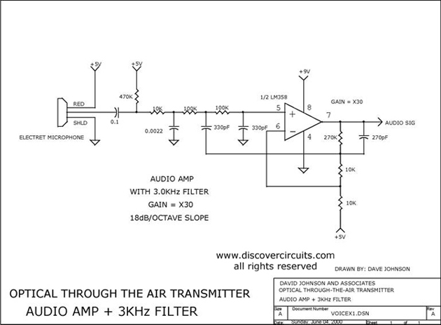
Audio amplifier with a 3 kHz filter. This circuit serves as the audio amplification section for a complete optical transmitter. It amplifies and filters voice audio signals from an electret microphone. The audio amplifier circuit is designed to enhance the...
Current loop analog data transmission is utilized in industrial environments due to its robustness, offering good noise immunity and the capability for wiring fault detection. Current loop analog data transmission systems are widely employed in industrial applications due to their...
The LM2002 / 2002A is an audio power amplifier integrated circuit. The LM2002A features high voltage protection, with a maximum instantaneous power supply voltage of up to 40V, and comes in a 5-pin single in-line plastic package. This integrated...
Here is an amplifier circuit based on the BUZ11, which can be replaced by an IRFZ34N, and an ECC83 can be used instead of the ECC88. In this case, the anode voltage should be reduced slightly to 155 V....
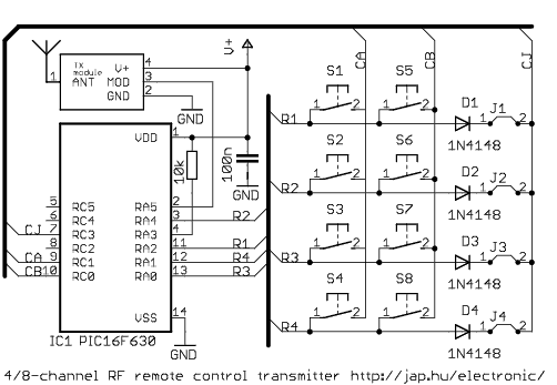
This is a general purpose remote control project with using programmable PIC microcontrollers. Schematics are shown for using infrared (RF) or radio (RF) media. If you are not familiar with microcontroller programming, you can use fixed encoder and decoder...

Transmitter RF Output LED Indicator Circuit Diagram. This RF output detector circuit, which includes a visual indicator, can be useful for an RF application. The transmitter RF output LED indicator circuit is designed to provide a visual representation of the...
Warning: include(partials/cookie-banner.php): Failed to open stream: Permission denied in /var/www/html/nextgr/view-circuit.php on line 713
Warning: include(): Failed opening 'partials/cookie-banner.php' for inclusion (include_path='.:/usr/share/php') in /var/www/html/nextgr/view-circuit.php on line 713