
TV Transmitter circuit diagram (VHF)
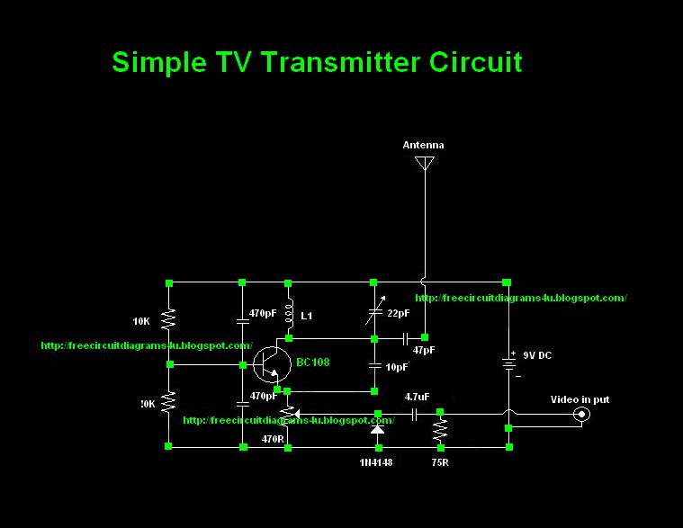
The TV transmitter circuit described is designed to operate effectively within a range of frequencies, allowing for versatile applications. The choice of the BC 108 transistor is significant due to its favorable characteristics for RF applications; however, alternatives like the BC337, 2N2222, and BC546 can also be employed without compromising performance. This flexibility in component selection aids in accessibility for builders who may not have the original transistor on hand.
The inductor L1 plays a crucial role in determining the operating frequency of the transmitter. The winding specifications are tailored to achieve specific frequency ranges: 6 turns for the lower band (60 - 80 MHz), 4 turns for the mid-band (150 - 180 MHz), and 2 turns for the upper band (180 - 200 MHz). The use of #24 enameled wire for winding ensures adequate inductance while maintaining a manageable size for the air former, which is essential for effective signal transmission.
The circuit's design emphasizes simplicity and functionality, making it suitable for hobbyists and those interested in exploring RF transmission. Proper assembly and tuning of the circuit will yield optimal performance, allowing users to transmit signals effectively over the stated distances. Additionally, the invitation for others to contribute their circuit designs fosters a collaborative environment, promoting knowledge sharing within the electronics community.Most of people ask TV transmitters. So Today I`m going to give you a very useful circuit diagram. By using this circuit you can send your signals 75m to 100m. This circuit diagram is not my own circuit one of my friends gave me this. I suppose you guys also can send your own circuit diagrams for us. Then we can publish them through our website. Here The y have used common transistor BC 108 If you are unable to find this transistor you can use equal transistors like Bc337 2n2222 Bc 546 # To make L1 wound 6 turns of #24 enameled wire on a 10mm air former for frequency 60 - 80 MHz For 150 - 180 MHz wound 4 turns and for 180 - 200MHz wound 2 turns. 🔗 External reference
Related Circuits
A, B, and C are used for a high-power split-phase system. The A + B' C' arrangement serves as a phase line for a range generator. The A-A' indole path string includes two 220V / 15W bulbs, which are...
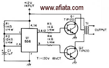
The first section of the 555 timer is configured as an astable oscillator, with R2 and C1 determining the frequency. The output is accessible at pin 5. The second section functions as a phase inverter, with its output available...
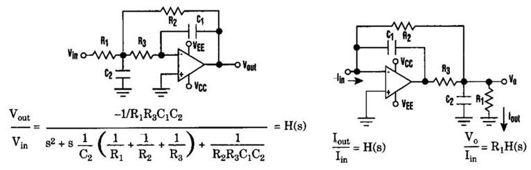
Current-Driven Sallen-Key Filter Circuit Diagram. The low-pass Sallen-Key filter is a staple for designers because it contains few components (A). The Sallen-Key filter is a widely used active filter topology that employs operational amplifiers (op-amps) to achieve desired filtering...
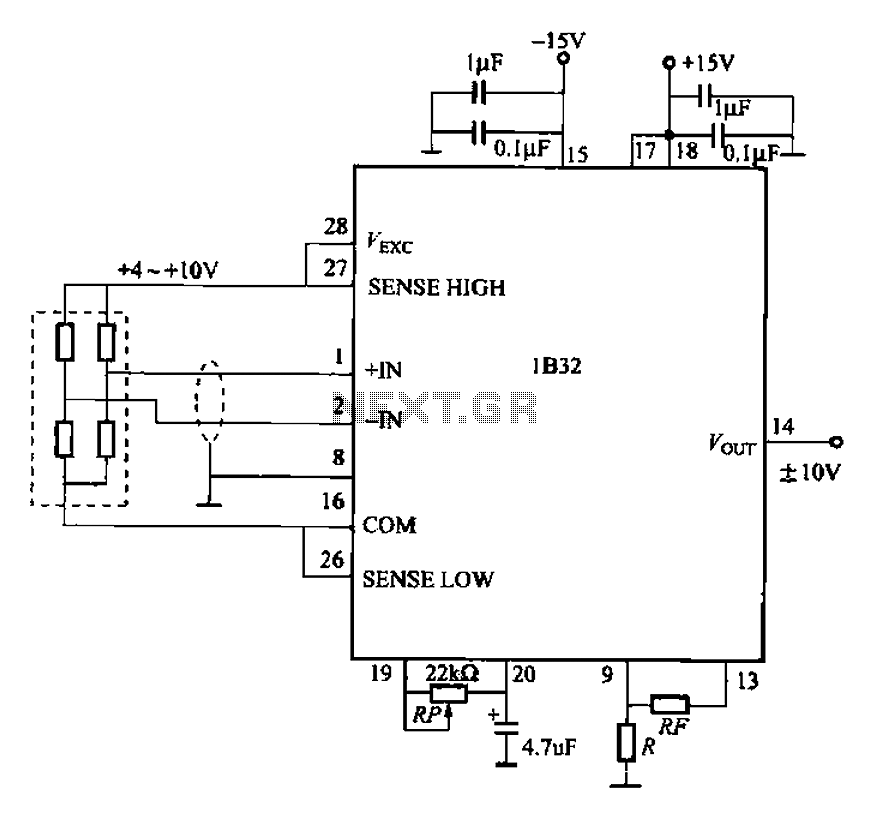
The circuit for bridge measurements is straightforward, as illustrated in the figure. The sensor bridge drive voltage can be adjusted between +4V and +10V, depending on the specific requirements of the sensor. Two fixed gain options of 333.3 and...
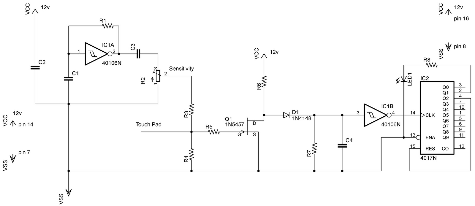
In the previous post regarding a capacitive touch switch, the output was activated only while the touch was maintained. This means that the circuit would drive the load only during the touch, and once the touch was removed, it...

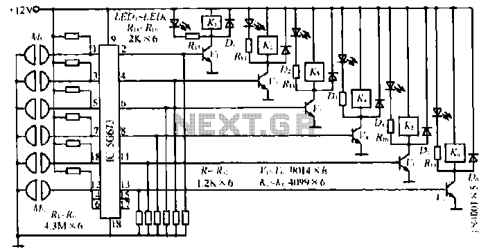
This 555 timer circuit temperature monitoring system project can monitor temperature at up to four points. The system allows for the selection of whether the alarm should be triggered when the temperature increases or decreases, depending on the resistance...
Warning: include(partials/cookie-banner.php): Failed to open stream: Permission denied in /var/www/html/nextgr/view-circuit.php on line 713
Warning: include(): Failed opening 'partials/cookie-banner.php' for inclusion (include_path='.:/usr/share/php') in /var/www/html/nextgr/view-circuit.php on line 713