
TW-42 FM radio transmitter high-frequency amplifier circuit section
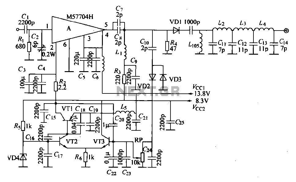
The FM radio transmitter circuit is designed to provide a reliable and efficient means of transmitting signals within the specified frequency range. The M57704H chip serves as the core component, functioning as a power amplifier that enhances the amplitude-modulated input signal. The choice of frequency range (457-458 MHz) is significant for compliance with regulatory standards and optimal performance in FM broadcasting.
The microstrip line used for matched filtering ensures that the signal maintains integrity and minimizes losses during transmission. This is crucial for maintaining signal quality and achieving the desired transmission range. The multi-section LC network, which is connected to VT1, plays a vital role in tuning the circuit to the desired frequency, allowing for effective modulation and transmission of the signal.
The detection paths involving VD2 and VD3 are integral for monitoring the output signal. These diodes convert the RF signal back into a DC voltage, which is then amplified by VT2 and VT3. This amplification is essential for providing feedback to the M57704H, ensuring that the power amplifier operates within its optimal range. The feedback loop is critical for maintaining consistent output power, which is particularly important in broadcasting applications to avoid signal distortion and ensure clear transmission.
The fixed power supply of 13.8V for the collector electrodes of the secondary amplifiers is a standard configuration that provides stable operation across various conditions. This voltage level is commonly used in RF applications, ensuring that the amplifiers operate efficiently without introducing additional noise or instability into the system.
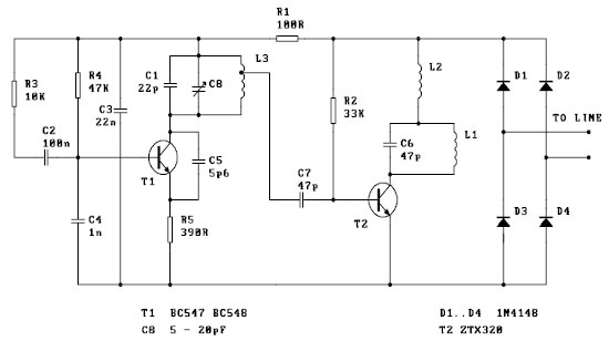
Overall, this FM radio transmitter circuit exemplifies a well-designed RF amplification system that effectively combines various components to achieve high-quality signal transmission while maintaining stability and performance.FM radio transmitter is a high-frequency amplifier circuit. This circuit uses Mitsubishi frequency set successfully discharge path M57704H. Using radio frequency modulation, th e operating frequency is 457-458MHz, transmit power is 5w. Seen from the figure, the input amplitude modulated signal through after M57704H power amplifier, all the way through a microstrip line matched filtering, and then after VT1 send a multi-section LC Ji-type network, and then transmitted by the antenna out; another path VD2, VD3 detection. VT2, VT3 After DC amplification, gave VT1 regulator, as the control voltage from M57704H feet first entered the first stage t adjust the power amplifier collector, can stabilize the entire integrated amplifier output power.
The second three amplifier collector electrode power supply is fixed 13. 8V.
Related Circuits
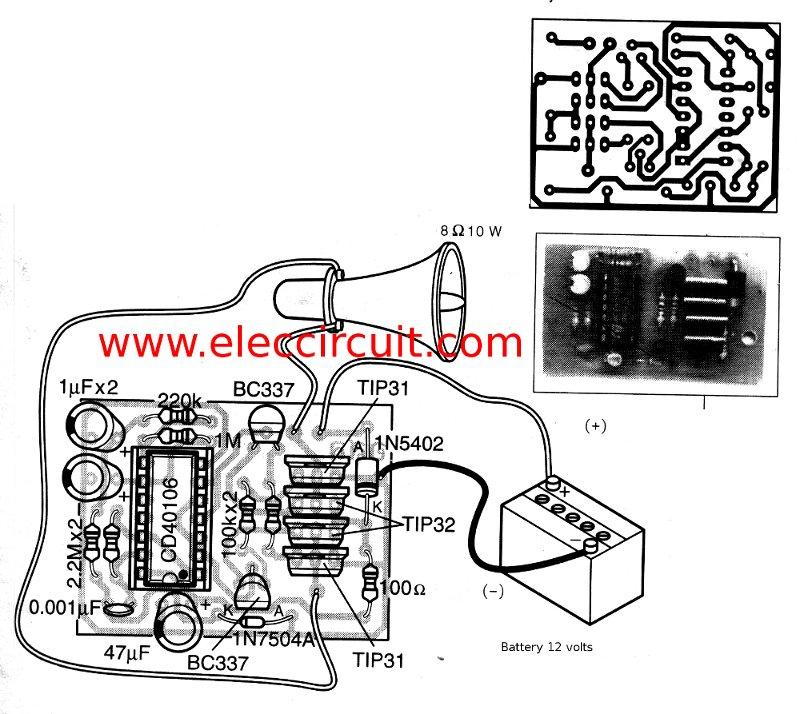
This is a simple siren sound generator with high power output and significant noise. The circuit utilizes digital ICs, specifically the CD4046, in an inverter configuration, along with four transistors to amplify the current output to a horn speaker...
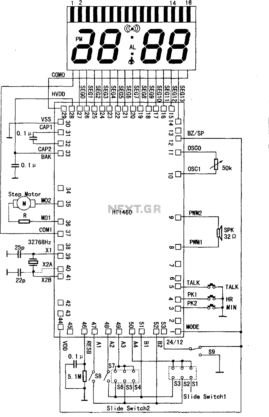
The speech synthesis circuit incorporates a microprocessor series, LCD drivers, a clock oscillator, input and output ports, memory, and a multi-voice audio signal amplifier circuit unit. This series circuit is primarily utilized in voice clocks, thermometers, electronic calendars, and...
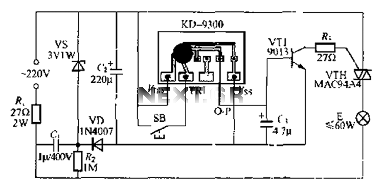
The circuit utilizes a KD-9300 music IC, which activates when the button switch (SB) is pressed, causing the electric lamp (E) to light up for approximately 20 seconds before automatically turning off. The setup includes a half-wave rectifier and...
This is a basic telephone broadcaster or transmitter designed for eavesdropping on telephone conversations. The circuit can also function as a wireless telephone amplifier. A key feature of this phone transmitter is that it derives its power directly from...
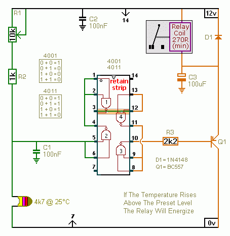
A CMOS 4001 or a CMOS 4011 can be utilized in this circuit, as both contain four two-input gates. The inputs of each gate are connected together, allowing them to function as simple inverters. This means that when both...
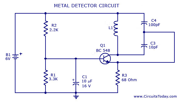
A simple metal detector circuit diagram and schematic using a single transistor and a radio. This metal detector/sensor project is easy to make and is an application of a Colpitts oscillator. The metal detector circuit utilizes a single transistor in...