
Two channel audio mixer circuit design electronic project
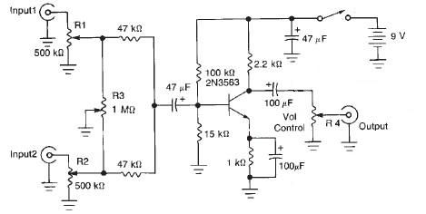
The audio mixer circuit is a versatile design that allows for the blending of two audio signals, making it suitable for various applications, including live sound reinforcement and studio recording. The circuit comprises two primary input channels, each equipped with a variable resistor (R1 and R2), which serves as a volume control for their respective audio signals. This configuration enables the user to adjust the amplitude of each input independently, facilitating a balanced mix.
The R3 variable resistor acts as a crossfader, providing a smooth transition between the two audio signals. By adjusting R3, one can gradually decrease the volume of one channel while simultaneously increasing the volume of the other. This feature is particularly useful in live performance settings where seamless audio transitions are required.
The 2N3563 NPN transistor is employed as the main amplification device in the circuit. It enhances the overall gain of the mixed audio signal, ensuring that the output maintains a sufficient level for further processing or amplification. The transistor's characteristics are well-suited for audio applications, providing low distortion and a wide frequency response.
Additional passive components, such as capacitors and resistors, may be included in the circuit to filter unwanted noise and stabilize the signal. Proper grounding and layout considerations are essential to minimize interference and ensure optimal performance. Overall, this audio mixer circuit is a practical and efficient solution for combining multiple audio sources, making it an excellent project for electronics enthusiasts and professionals alike.This audio mixer circuit diagram electronic project is designed using few common electronic components. This audio mixer circuit project has two input channels. The input signal can be independently controlled using the R1 and R2 variable resistors. The R3 variable resistor offers possibility to fade out one of the signal while the other signal is fading in. The gain of the mixer is provided by the 2N3563 NPN transistor. 🔗 External reference
Related Circuits
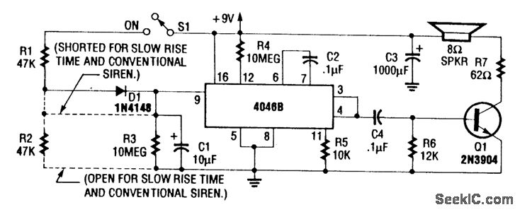
For a normal wailing tone, short D1 and leave R2 open. To achieve a fast rise and slow fall in frequency, include both D1 and R2. Utilizing a CD4046B with a diode-RC network as illustrated generates a siren tone...
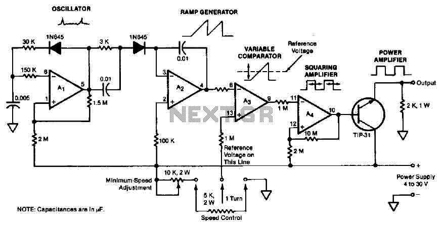
The quad operational amplifier circuit provides a pulse width modulation control ranging from 0 to 100 percent. The controller utilizes an LM3900 and operates with a single supply voltage between 4 to 30 V. A 1 kHz oscillator amplifier,...
The circuit for the power amplifier has a power output of up to 1500W RMS and is commonly utilized in outdoor sound systems. The final image displays a series of power amplifiers that utilize 10 sets of power transistors....
This circuit utilizes two operational amplifiers (op-amps) to create a unique sound effect. The first op-amp, CA741, is configured as a standard astable multivibrator, generating timing pulses controlled by components C1, R2, and variable resistor VR1. The output from...
The TBA120 Series integrated circuits (ICs) offer a high-gain limiting intermediate frequency (IF) amplifier and a quadrature coincidence detector in a single package. These ICs are primarily designed for the extraction of television intercarrier sound, which is frequency modulated...
This LED (Light Emitting Diode) display consists of 10 LEDs to indicate the level of an input signal. If the signal is low, only LED #1 will light up. As the signal level increases, the illuminated dot will progress...
Warning: include(partials/cookie-banner.php): Failed to open stream: Permission denied in /var/www/html/nextgr/view-circuit.php on line 713
Warning: include(): Failed opening 'partials/cookie-banner.php' for inclusion (include_path='.:/usr/share/php') in /var/www/html/nextgr/view-circuit.php on line 713