
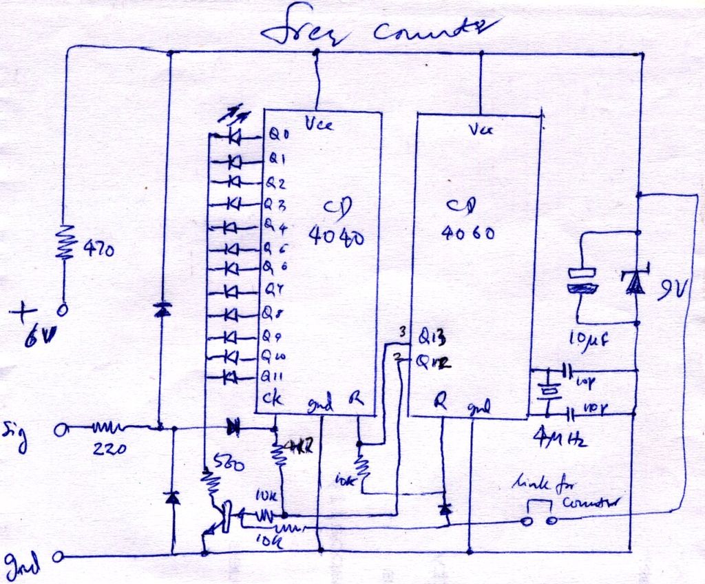
Two chip Frequency Meter with binary readout circuit
The circuit diagram represents a critical stage in the development of an electronic project, serving as a blueprint for the physical layout and interconnections of components. It typically includes various elements such as resistors, capacitors, transistors, and integrated circuits, which are essential for the intended functionality of the device.
The diagram should clearly indicate the connections between components, ensuring that the flow of current is accurately represented. Each component is usually labeled with its value or part number, facilitating easy identification during assembly and troubleshooting. Additionally, the power supply connections must be clearly marked to avoid any potential errors that could lead to circuit failure.
In a well-documented circuit diagram, the orientation of polarized components, such as electrolytic capacitors and diodes, must be specified to prevent incorrect installation. Furthermore, signal flow direction might be indicated with arrows, enhancing clarity for users who will implement the design.
Proper scaling of the schematic is also essential, as it allows for easier reading and understanding of the circuit's complexity. A legend or key may be included to explain any symbols used, ensuring that the diagram is accessible to individuals with varying levels of expertise.
Overall, a comprehensive circuit diagram not only aids in the construction process but also serves as an invaluable reference for future modifications or repairs. It encapsulates the design intent and functional requirements, forming the foundation for successful electronic project execution.Now, when the construction is nearly done, here is a circuit diagram. When I finally settled on how it was going to be done, and set it down on paper,.. 🔗 External reference
Related Circuits
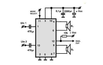
A simple Class B power amplifier can be constructed using the TDA8560 audio integrated circuit (IC). The TDA8560 amplifier features an internally fixed voltage gain, ensuring excellent channel balance. This audio amplifier project is capable of delivering dual 40-watt...
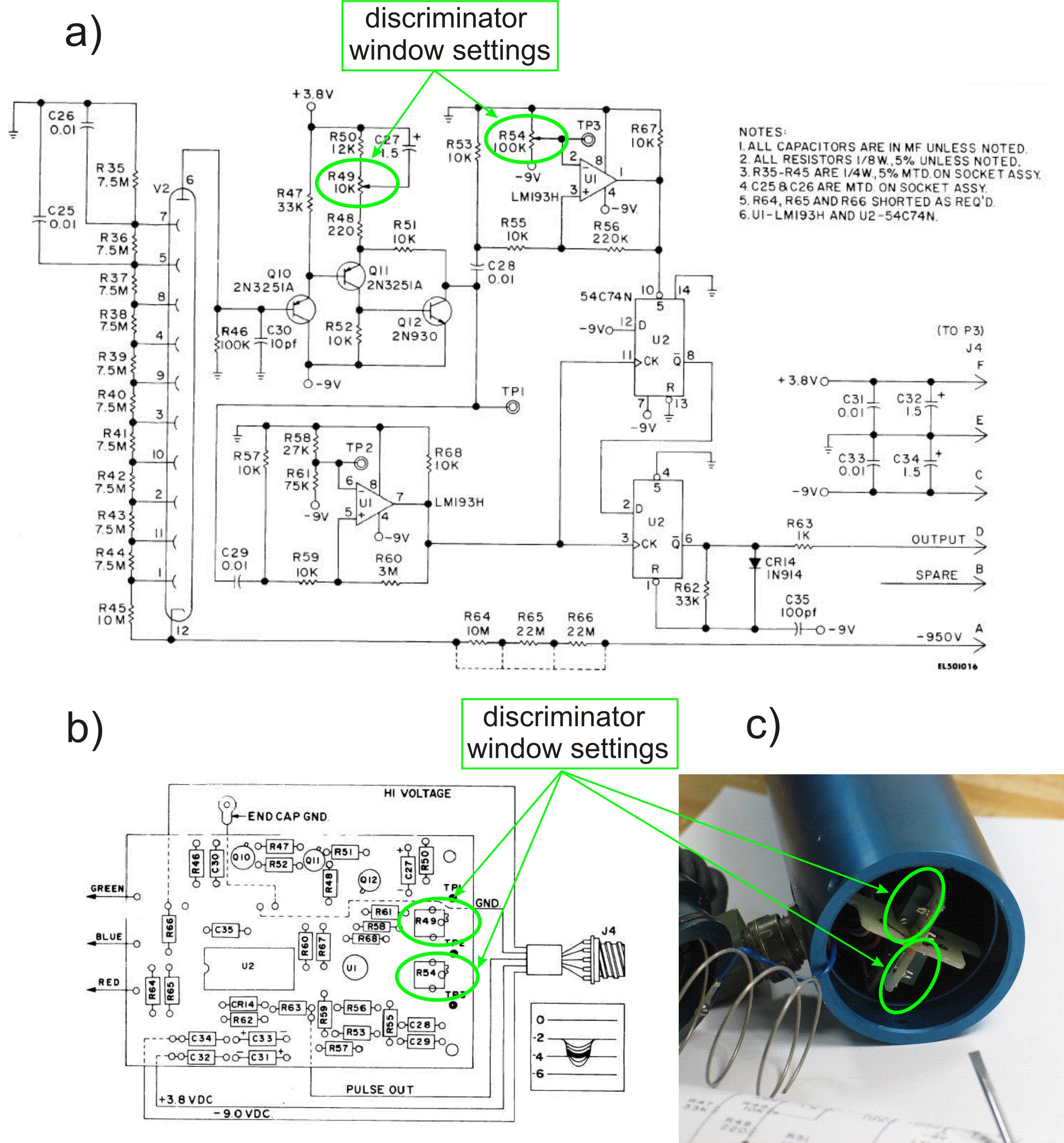
This PDF file presents the schematic diagram of a custom-built circuit designed to drive the PDR-56 probe. A JKL BXA-12579 inverter, typically used for powering cold-cathode fluorescent lamps, serves as the high-voltage power supply. The BXA-12579 generates 1,500 VAC...
This circuit regulates a DC power output and has a wide range of applications. It can be utilized to control the speed of a motor, a pump, a toy train, or the brightness of an LED or lamp. Essentially,...
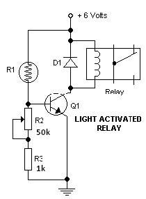
This light-dark switch activated relay circuit schematic represents one of the simplest electronic circuits designed to activate other electronic devices based on light or darkness. It requires a single electronic relay and a few common components that are not...
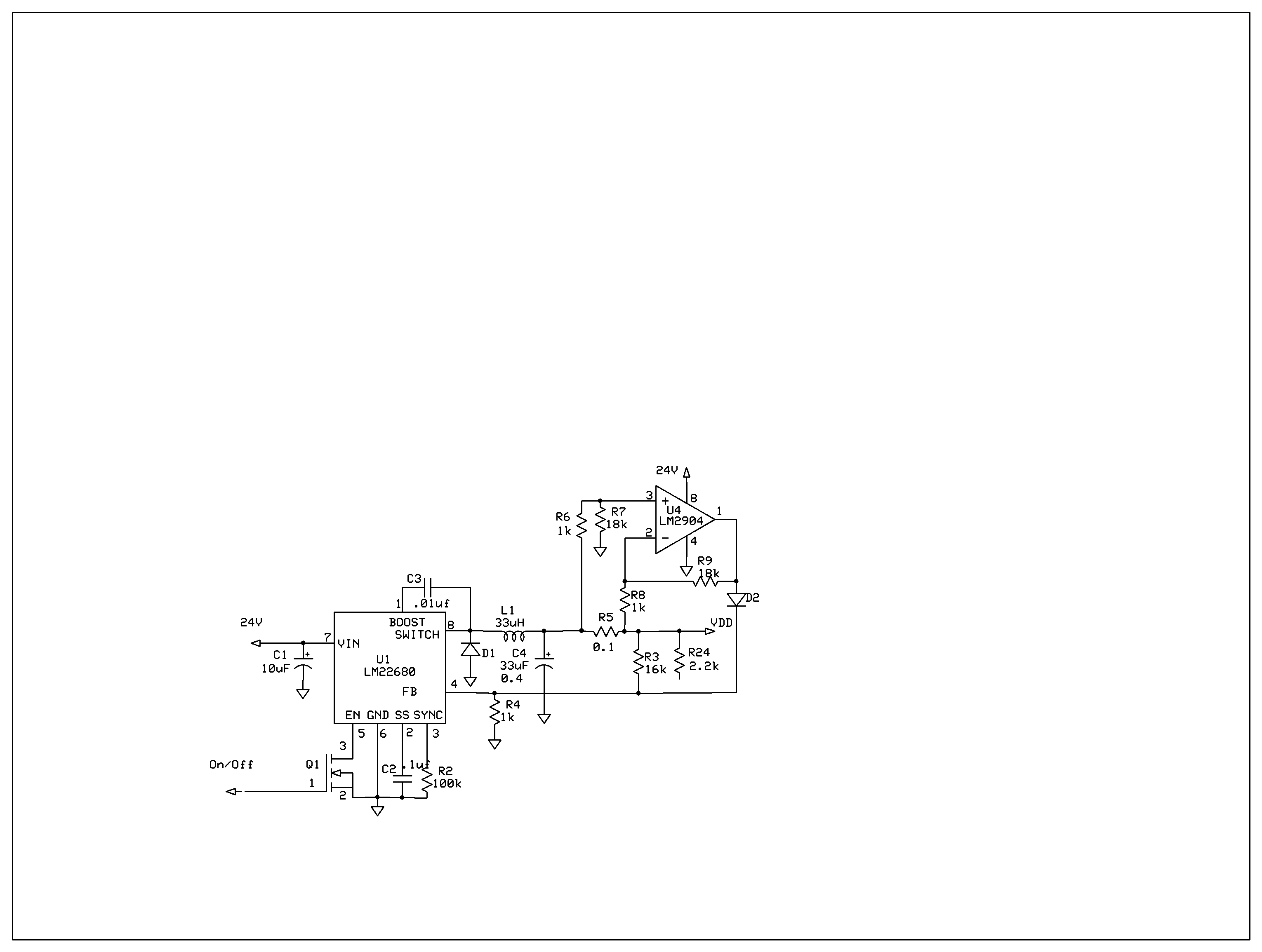
The product requires a voltage-controlled, current-limited power supply. Various switcher chips have been used with an op-amp to provide feedback for a current sense voltage to the feedback pin. Currently, an LM22680 is in use, but it has shown...
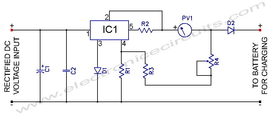
L200 12V Constant Voltage Battery Charger Circuit. This battery charger is based on the L200 regulator IC. The L200 is a five-pin adjustable voltage regulator. The L200 constant voltage battery charger circuit is designed to provide a stable 12V output...
Warning: include(partials/cookie-banner.php): Failed to open stream: Permission denied in /var/www/html/nextgr/view-circuit.php on line 713
Warning: include(): Failed opening 'partials/cookie-banner.php' for inclusion (include_path='.:/usr/share/php') in /var/www/html/nextgr/view-circuit.php on line 713