
Two electric motors or electrical interlocking control circuit
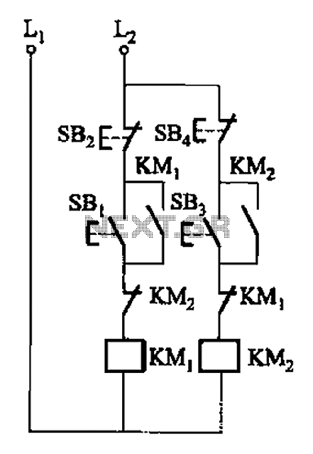
The circuit design facilitates the interlocking operation of two electric motors, referred to as Motor A and Motor B, ensuring that both motors can operate simultaneously without causing electrical faults or mechanical interference. The interlock control system is achieved through the use of normally closed contacts, which are integrated into the coil circuit of each motor.
In this configuration, the normally closed contacts are connected in series with the coils of the motors. When Motor A is energized, the current flows through its coil, causing it to operate. However, the normally closed contact associated with Motor B remains closed, allowing the current to flow to Motor A while preventing Motor B from being activated simultaneously. This arrangement ensures that if one motor is running, the other cannot be activated, thereby preventing potential overload or mechanical failure.
The circuit can be designed using relays or contactors that feature normally closed contacts. Each motor coil is connected to its respective relay, and the relay contacts are wired to form an interlock. This means that when one relay is energized, it opens the circuit for the other relay, effectively preventing both motors from running at the same time.
Additionally, this configuration can be enhanced with safety features such as overload protection and emergency stop buttons. These components can be integrated into the circuit to provide further reliability and safety during operation. The interlock control system is particularly useful in applications where motors must not operate simultaneously due to load constraints or mechanical coupling, ensuring a safe and efficient operational environment.A, B and two electric motors (or electronic) allowed simultaneous operation (interlock control). The two motors can (or electronic) of the respective contact normally closed co ntacts in series with each other interchangeably coil circuit,
Related Circuits
The primary function of the optical receiver is to extract information encoded on a modulated light carrier from a distant transmitter and restore it to its original form. A typical through-the-air communications receiver can be divided into five distinct...
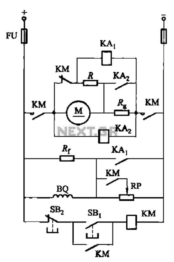
The circuit illustrated in Figure 3-197 features a dish adjust rheostat (RP) that allows for the adjustment of field current, which in turn modifies the motor speed. The circuit operates by utilizing a rheostat, which is a variable resistor that...
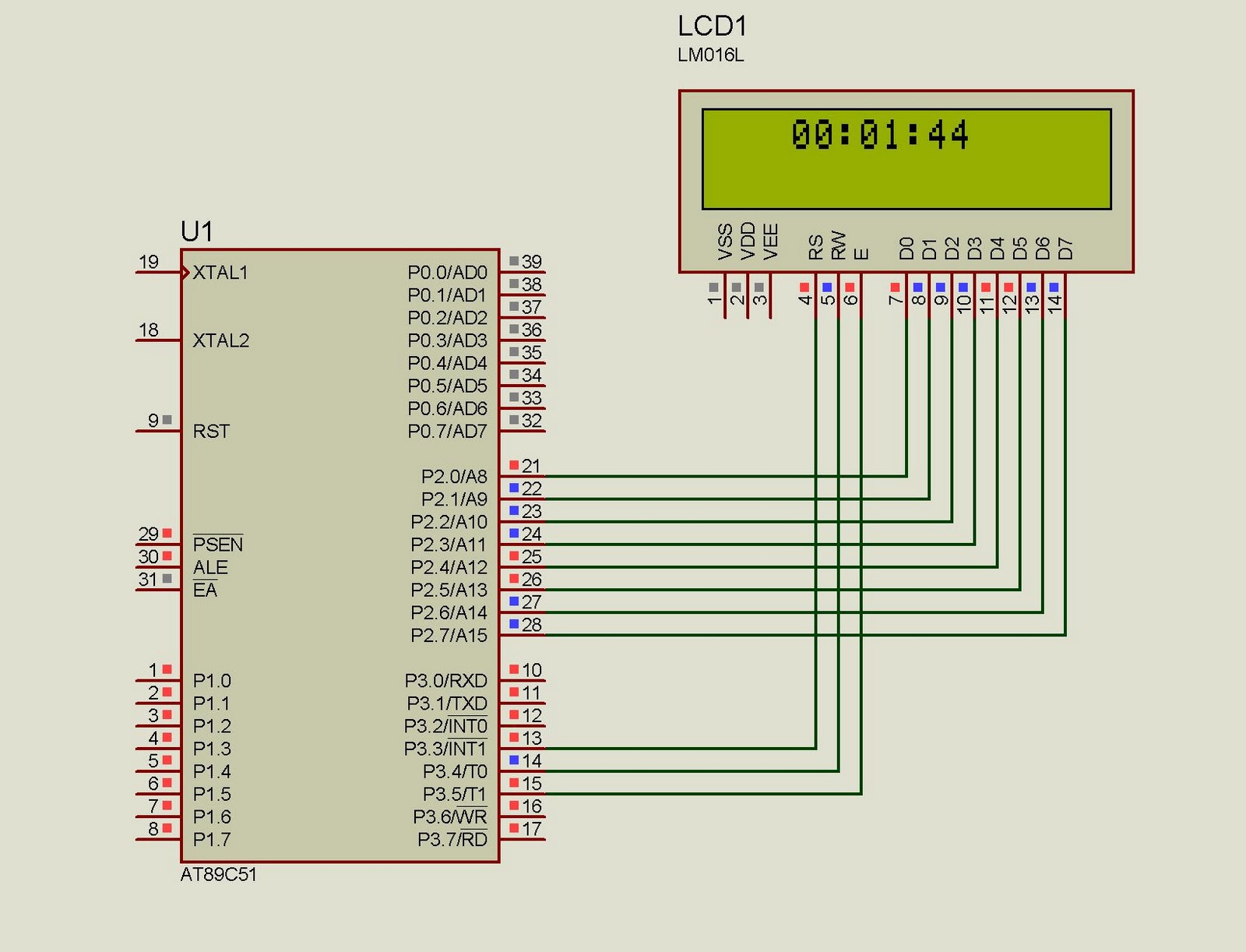
This project implements a real-time clock using the 89C51 microcontroller. The clock's data format is hours:minutes:seconds, which is displayed on a 16x2 LCD. The code has been tested and compiled using the Keil uVision compiler. The circuit diagram for...
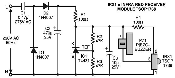
Remote control tester circuit diagram. The tester is designed around the infrared receiver module TSOP1738. The operation of the remote control is indicated by a tone from the buzzer. The circuit is sensitive and has a range of about...
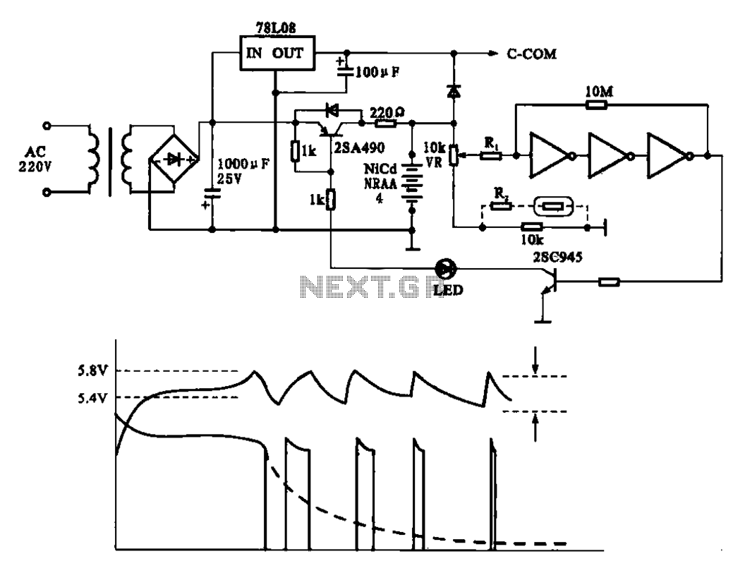
Fast charging circuit that illustrates voltage and current waveforms along with the configuration of the fast charge circuit for the charger. The detection and control circuit consists of three inverters (GMOS) from integrated circuits, enabling automatic control functions. The fast...
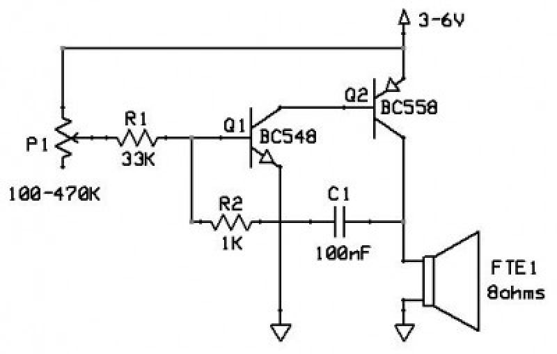
This circuit functions as an oscillator, capable of generating a sound wave or tone. The frequency of the tone, whether high or low, is adjustable via a variable resistor. The volume produced by this circuit is substantial; therefore, it...
Warning: include(partials/cookie-banner.php): Failed to open stream: Permission denied in /var/www/html/nextgr/view-circuit.php on line 713
Warning: include(): Failed opening 'partials/cookie-banner.php' for inclusion (include_path='.:/usr/share/php') in /var/www/html/nextgr/view-circuit.php on line 713