
Two Interlocked Toggle Switches - Cmos 4013
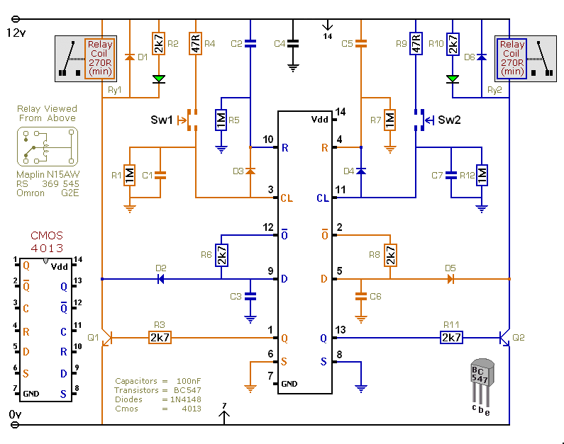
This circuit is designed to provide flexibility in controlling devices, particularly in applications involving DC motors. The use of diodes allows for interlocking functionality, ensuring that only one relay can be activated at a time, which is crucial for applications that require directional control of motors. The diodes (D2, D3, D4, D5) play a significant role in preventing back-feeding of voltage from one relay to another, thus enhancing the reliability of the switching mechanism.
The relays used in this circuit should be chosen based on the operational requirements, including the current and voltage ratings necessary for the load being controlled. The recommendation to avoid using on-board relays for mains voltage switching is critical for safety, as insufficient isolation could lead to hazardous conditions.
The circuit's center-off position is particularly useful for applications requiring a neutral state, where both relays are de-energized. This feature allows for a safe transition between states without the risk of unintended activation of either relay.
In summary, this circuit is a robust solution for applications requiring controlled switching of DC devices, providing both versatility and safety through its innovative design and component selection. Proper implementation will ensure effective operation within the specified voltage range, and adherence to safety guidelines will mitigate risks associated with high-voltage applications.This versatile circuit provides a selection of different switching modes. It can be used as two entirely separate toggle switches - with each push button successively energizing and de-energizing its own relay. Or the two switches can be interlinked with diodes - to produce a number of different switching patterns.
For example - the circuit can be used to reverse the direction of DC motors. D3 allows the orange push button to de-energize the blue relay. And D4 allows the blue push button to de-energize the orange relay. In other words - if the blue relay is energized - it will drop out when you press the orange button. And - if the orange relay is energized - it will drop out when you press the blue button. While the blue relay is energized - D5 & Q2 hold the orange data pin low. This prevents the orange push button from energizing the orange relay. Similarly - while the orange relay is energized - D2 & Q1 hold the blue data pin low. So the blue push button can`t energize the blue relay. In other words - the two relays can`t be energized at the same time. You have to de-energize the first - before you can energize the second. And vice versa. I`ve drawn the circuit with all four diodes present. And the accompanying Flow Chart describes how each switch will behave. Basically - each button will toggle its own relay. But you can`t switch directly from one relay to the other. There`s a "centre-off" position - when both relays are de-energized. The circuit will work at anything from 5 to 15-volts. All you need do is choose relays with a coil voltage that suits your supply. I`ve drawn single pole relays. But you can use multi-pole relays - if they suit your application. Do not use the "on-board" relays to switch mains voltage. The board`s layout does not offer sufficient isolation between the relay contacts and the low-voltage components. If you want to switch mains voltage - mount suitably rated relays somewhere safe - Away From The Board.
🔗 External reference
Related Circuits
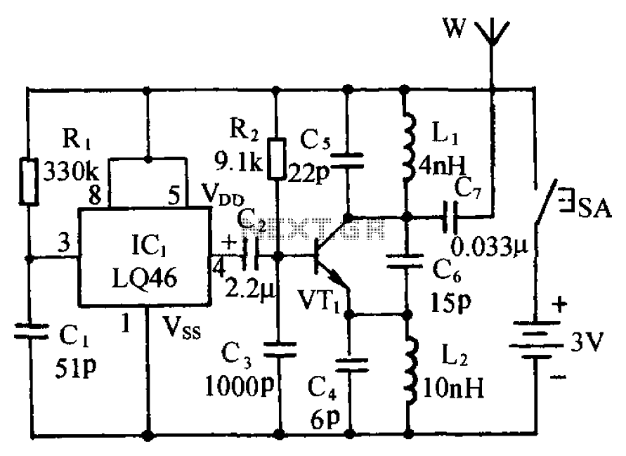
The circuit is presented, consisting of a language and sound circuit FM transmitter. It is simple and easy to manufacture, compatible with ordinary FM radios, allowing for potential listening scenarios and preventive measures. The FM transmitter circuit is designed to...
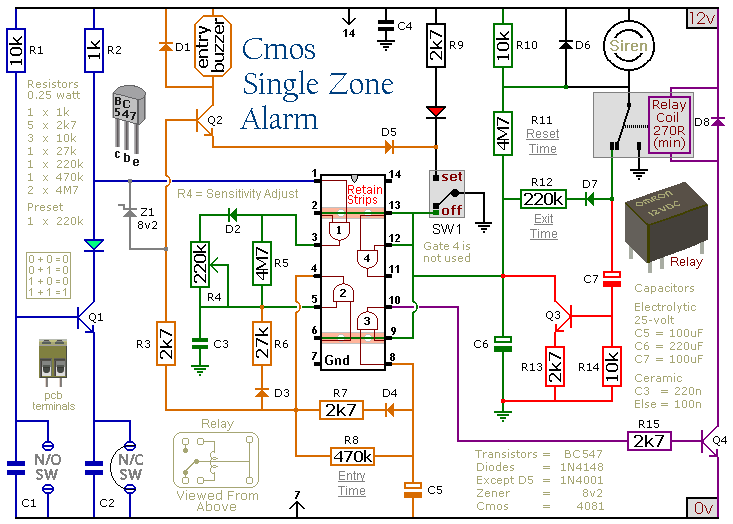
This circuit features automatic Exit/Entry delays, timed Bell Cut-off and System Reset. It has provision for normally open and normally closed switches and will accommodate the usual input devices such as Foil Tape, Pressure Mats, Magnetic Reed Contacts, Passive...
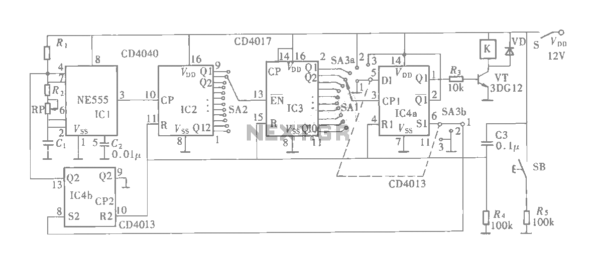
The multifunction circuit primarily refers to its capability to operate in three modes: "delayed pull," "time release," and "delayed cycle." The term "delay" indicates that the relay is energized after a predetermined time; however, the relay does not activate...
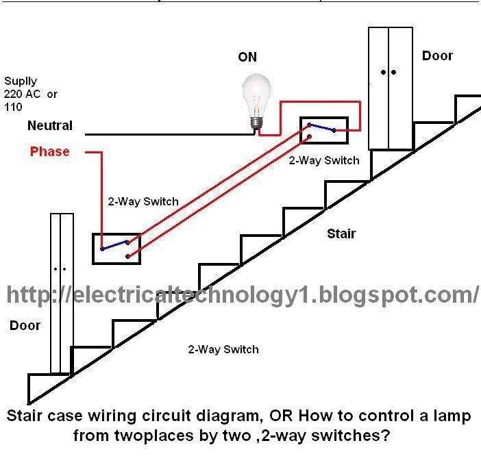
The circuit is complete, and the bulb is ON. To turn OFF the bulb from the upper switch at the top of the stairs, simply turn OFF the switch, which will break the circuit and turn the bulb OFF....
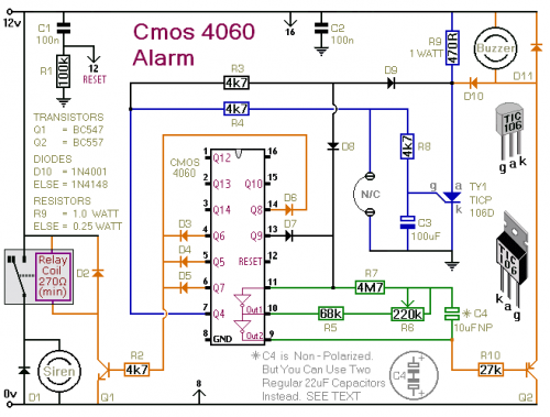
This is a single-zone alarm system featuring automatic exit, entry, and siren cut-off timers. It accommodates various types of normally-closed input devices, including magnetic reed contacts, foil tape, passive infrared sensors (PIRs), and more. Additionally, it is straightforward to...

This circuit is similar to the one above, but uses a N channel mosfet such as IRF530, 540, 640, etc. in place of the NPN transistor. Smaller mosfets could be used, but I don't know the part numbers. I...