
Two line intercom plus a telephone changeover switch
The two-line intercom circuit is designed to facilitate communication between two separate locations while also allowing the integration of a standard telephone line. The primary function of this circuit is to enable users to communicate with each other via two intercom units while maintaining the capability to switch to a telephone line when necessary.
The circuit consists of two main components: the intercom units and the changeover switch. Each intercom unit is equipped with a microphone and speaker, allowing for two-way communication. The changeover switch is responsible for toggling the connection between the intercom system and the telephone line.
In operation, when the intercom is in use, pressing a button on either unit activates the microphone and speaker, allowing users to converse. The changeover switch can be activated to connect one of the intercom units to an external telephone line, enabling the user to make or receive calls.
The circuit typically employs standard components such as resistors, capacitors, and transistors to amplify the audio signals and manage the switching mechanism. It is essential to ensure that the components are rated for the appropriate voltage and current levels to avoid damage during operation.
In summary, this two-line intercom with a telephone changeover switch offers a versatile solution for intercommunication and telephone access, making it suitable for residential or small business applications. Proper installation and component selection are crucial for optimal performance and reliability.Two line intercom plus a telephone changeover switch. The circuit presented here can be used for connecting two telephones in parallel and also as a 2-line intercom. Usually a single telephone is connected to a. 🔗 External reference
Related Circuits
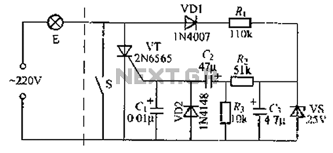
A delay circuit using an improved quenching lamp pull switch is described, focusing on its performance and the delay function in lighting control. The circuit exhibits a high degree of stability and reliability. When switch S is closed, the...
The system utilizes the DSP56F826 chip as the primary control module and incorporates a CMOS digital image sensor capable of capturing images with a resolution of 640 x 480 pixels. For applications requiring higher resolution, a chip supporting 1024...
This is a 220V touch switch circuit. This circuit functions as a switch that turns off and on the electronic device connected to the 220V home supply. The 220V touch switch circuit is designed to control the operation of electrical...

This circuit is a simple telephone ringtone generator designed using minimal components. It produces a simulated telephone ringing tone and operates on a DC voltage ranging from 4.5V to 12V. This circuit can be utilized in standard intercom systems...
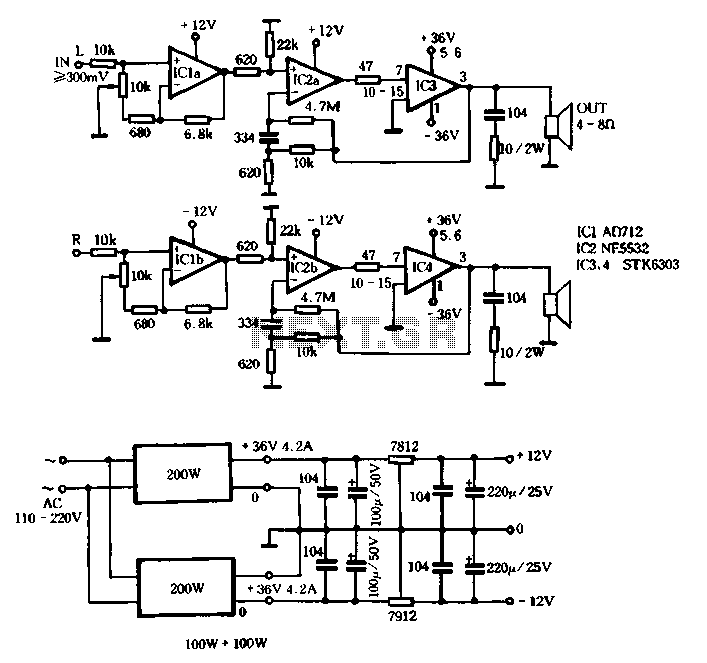
The T amplifier circuit schematic section is illustrated in Figure 3-51. It utilizes the Japan Sanyo STK6303 Pina, which is a high-power thick film integrated circuit. The maximum power supply voltage is 36V, and the output current can reach...
Utilizes two distinct common-cathode video mixers. Identical heading markers are inserted into the front input 2 of both mixers, while the other inputs manage independent markers. The circuit employs two common-cathode video mixers, which are integral components for combining multiple...
Warning: include(partials/cookie-banner.php): Failed to open stream: Permission denied in /var/www/html/nextgr/view-circuit.php on line 713
Warning: include(): Failed opening 'partials/cookie-banner.php' for inclusion (include_path='.:/usr/share/php') in /var/www/html/nextgr/view-circuit.php on line 713