
TWO OUADRANT EXPONENTIAL CONTROL
05 and 10 V. (View) The input pulse is fed into the sample-and-hold amplifier (an inexpensive AD582), as well as the compa rator U3. The SHA`s output also is fed into the comparator. If the input pulse is higher in am-plitude than the SHA`s output, the comparator output goes low and the 4538 one-shot produces a l0-ps pulse that is fed back to cause the SHA to sample and then hold the voltage. Subsequent input voltages that are less than the held value won`t cause the one-shot to fire again. Gates U4A and U4B are used to inhibit the sampling when necessary. Gates U4C and U4D, at the one-shot`s output, can force the AD 582 into the sample mode. This feature is useful to reset the output to zero by forcing a sample when the input to the AD582 is zero.
The polarity of the peak-hold circuit can be easily changed from positive-to-negative peak hold by reversing the inputs of the comparator. (View) This regulator uses the drop across R3 to sense current draw, turning on Q2, removing drive from Q1, and lowering the output voltage.
Limiting occurs when Q2 has 0. 65 V across the base-emitter junction. This circuit has foldback characteristics as seen from the figure. (View) The circuit has a duty-cycle generator that will produce an output varytng from fully off to fully on and pulses of any duty cycle in between the two extremes. This method of operation is called PWM (pulse zuidth moduhtion) The circuit can be fed fromany dc supply source of between 10 to 15 V Half of an LM556 dual oscillator timer and U2 a(1/4 of an LM339 quad comparator) combine to form a voltage to-pulse-width converter The first half of thedual os dilator/timer(U1-a) is configured as an astable oscillator generating a continuously oscillating ramp voltage Op amp U2-a compares the voltage at its noninverting input (pin 5) ”which is connected to pins 2 and 6 of U1-a ”to the voltage at its inverting input(pin 4) The op amp will producea low output f R1`s wiper voltage lb higher than the instantaneous voltage that is present at pins 2 and 6 of U1-a The output of U2-a at pin 2 will have an on/off ratio that is proportional to the voltageat R1 ‡s wiper.
The output of U2-a is fed to U1-b which is used to buffer the signal The low impedance pulsedoutput of U1-b at pin 9 is fed to the gate of MOSFET Q1 driving it on or off The circuit also has apower-input detector built around U2-band and LED1. If the input power is OK LED1 will shut off. Diode D1 is used to Suppress the reverse voltage spikes that are generated by inductive loads during turn off ›without that diode the MOSFET might be destroyed If the circuit will not be usedto drive inductive loads(motors) D1 can be eliminated.
(View) A common collector amplifier drives a 2N3904 switch to sound alarm BZ1. The wire leads to wa-ter sensor or surnp pit, level switch, etc. and used to allow the alarm to operate and be mounted in a dry place. (View) This circuit is used to vary the power delivered to a 120-Vac load under software control. A 68705 micro controller can control eight discrete power triacs, each of which delivers power in 82 smoothly graduated steps, ranging from 0 to 97% of full power. The value delivered to one channel is independent of the value delivered to any other channel. Loads can include light displays, universal motors, heaters, and other appliances. The power level is set by software, not a potentiometer. The software includes a basic set of routines for processing interrupts and setting the power level. The software also includes five test and demonqtration routines for putting the circuit through its paces.
Moreover, there`s plenty of room to add your own routines to the 68705`s built-in EPROM. The basic circuit 🔗 External reference
Related Circuits
A request has been made to automate certain functions within a residence, specifically to control the on and off states of CFL lamps using a triac that is coupled to a logic circuit via a zero-crossing detection mechanism. To achieve...
This project was begun as a means to charge and cycle NiCad batteries but has become a versatile tool for experiments requiring either a controlled voltage up to +30V and/or a current of +/- 2.5 Amps. If all you...
The input mentions the 89S51/52 microcontrollers, but the accompanying image shows the 89C51. Clarification is needed regarding which microcontroller should be used with the provided .hex file without requiring changes to the file. The 89S51 and 89S52 are part of...
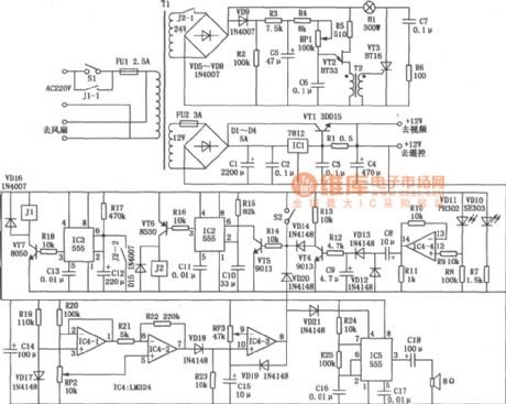
This circuit allows for the adjustment of fan speed from a distance, such as from a couch or bed. It utilizes the TSOP1738 infrared receiver module to capture the infrared signals. The circuit operates by employing an infrared remote control,...
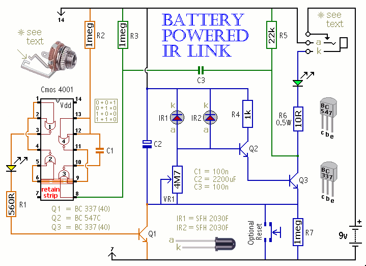
This is a battery-powered infrared (IR) link that can be utilized in multiple rooms. The standby current is exceptionally low, resulting in excellent battery life. The circuit is designed to shut down when faced with extraneous IR radiation, effectively...
An operational amplifier such as the NE5532 should be used. The desired frequency must be calculated for each block: one for flat, one for bass, and one for high frequencies. It is important to include a buffer at the...