
Two Simple Relay Based Motorcycle Alarms circuit
Relays serve as critical components in motorcycle alarm systems, providing both functionality and security. The choice of relay type, whether SPCO/SPDT or DPST, directly influences the circuit's operation and reliability. The design allows for flexibility in component selection, enabling users to adapt the system to their specific needs.
In the schematic, the integration of normally-open switches enables the detection of unauthorized movement or tampering. Positioning mercury switches strategically ensures that the system responds promptly to changes in the motorcycle's orientation, enhancing security. The use of micro-switches offers additional layers of protection for components that may be easily removed or accessed.
The decision to implement a continuous or momentary alarm response is a crucial design consideration. By configuring the circuit to allow for manual override or automatic shut-off, the system can be tailored to various scenarios, balancing security with user convenience. The inclusion of a SPST switch provides a user-friendly means to toggle between these operational modes, adapting to the owner's preferences.
Protection against voltage spikes is paramount in maintaining the integrity of the alarm system. The diodes serve as a safeguard, ensuring that any reverse voltage generated during relay operation does not affect sensitive components. This precaution is especially vital in environments where multiple electronic devices may share the same power supply, as it mitigates the risk of unintended damage.
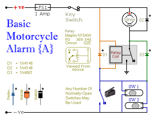
Overall, the described alarm system exemplifies a robust and adaptable solution for motorcycle security, combining compact design with versatile functionality to meet the diverse needs of motorcycle owners.You can use them to protect your motorcycle but have many more applications. If you use relays with 6-volt coils - they`ll protect your "Classic Bike". Both alarms are very small. The completed boards occupy about half a cubic-inch - 8 cc. The standby current is zero - so they won`t drain your battery. Circuit Number Five uses a SPCO/SPDT relay - but you really only need to use a SPST relay. If you are going to use the veroboard layout provided - you`ll need to use the style of relay specified. But you can build the alarm using whatever style of relay you have available. Any number of normally-open switches may be used. Fit the mercury switches so that they close when the steering is moved or when the bike is lifted off its side-stand or pushed forward off its centre-stand.
Use micro-switches to protect removable panels and the lids of panniers etc. When one of the trigger-switches is closed - the relay will energize and the siren will sound. You can choose what happens next. If you build the circuit as shown, the siren will continue to sound until you turn it off - or until the battery is exhausted. But, if you leave out D3 - the siren will stop sounding immediately the trigger-switch is re-opened. While you`re within earshot of your machine - the former configuration is best. You can always turn off the alarm yourself. But if you are going to be away from your bike for any length of time - and you don`t want to cause a nuisance - then the latter configuration is probably more suitable.
If you include a SPST switch in series with D3 - you can select the behaviour that best suits the circumstances at any given time. Relay coils and some sounders produce high reverse-voltage spikes that will destroy sensitive electronic components.
D1 and D2 are there to short-circuit these spikes before they can do any damage. Although there is nothing in the alarm circuit itself that could be damaged - I have no idea what other electronic equipment might be connected to the same power supply. So I included the two diodes as a precaution. If you`re satisfied that there`s nothing on your bike that might be damaged in this way - you can leave out the two diodes.
Circuit Number Six uses a DPCO/DPDT relay - but you really only need to use a DPST relay. If you are going to use the veroboard layout provided - you`ll need to use the style of relay specified. But you can build the alarm using whatever style of relay you have available. Any number of normally-open switches may be used. Fit the mercury switches so that they close when the steering is moved or when the bike is lifted off its side-stand or pushed forward off its centre-stand.
Use micro-switches to protect removable panels and the lids of panniers etc. When one of the trigger-switches is closed - the relay will energize and the siren will sound. You can choose what happens next. If you build the circuit as shown, the siren will continue to sound until you turn it off - or until the battery is exhausted. But, if you leave out the (yellow) solder-bridge in the top left-hand corner of the diagram - the siren will stop sounding immediately the trigger-switch is re-opened.
While you`re within earshot of your machine - the former configuration is best. You can always turn off the alarm yourself. But if you are going to be away from your bike for any length of time - and you don`t want to cause a nuisance - then the latter configuration is probably more suitable. Connect a SPST switch in place of the (yellow) solder-bridge - and you can select the behaviour that best suits the circumstances at any given time.
Relay coils and some sounders produce high reverse-voltage spikes that will destroy sensitive electronic components. D1 and D2 are there to short-circuit these spikes before they can do any damage. Although there is nothing in the alarm circuit itself that could be damag 🔗 External reference
Related Circuits
Motorcycle battery charger power supply. Refer to the mentioned page for an explanation of the power supply related circuit diagram. The description of the battery charger indicator: The circuit above enhances the appearance of a simple battery charger, making...

A 555 timer configured as an astable multivibrator is used in this circuit to generate an audio note. The capacitance value can be changed to vary the audio note as desired. The circuit utilizes a 555 timer IC, which...
The schematic diagram is straightforward. SW1 is a pushbutton used to start the timer. The outputs are set to logic level 0 when the timer is inactive and to logic level 1 when the timer is triggered. The relay...
A button is utilized as a push-to-talk switch. While it generally functions correctly, there is a significant delay of approximately five seconds before any audio output is heard upon pressing the button. The described circuit involves a push-to-talk switch, which...

A Zener diode regulator is a fundamental electronic circuit valuable for hobbyists. This circuit provides a regulated output voltage, suitable for biasing other circuit components. The Zener diode operates in the reverse breakdown region, maintaining a nearly constant voltage...

The AD594/595 can be configured to measure temperature in Celsius. In the circuit diagram, the IN+ and IN- terminals should be shorted to the COM terminal. The output voltage (Uo) has a temperature coefficient of 10 mV/°C, which can...