
Two-tone-siren
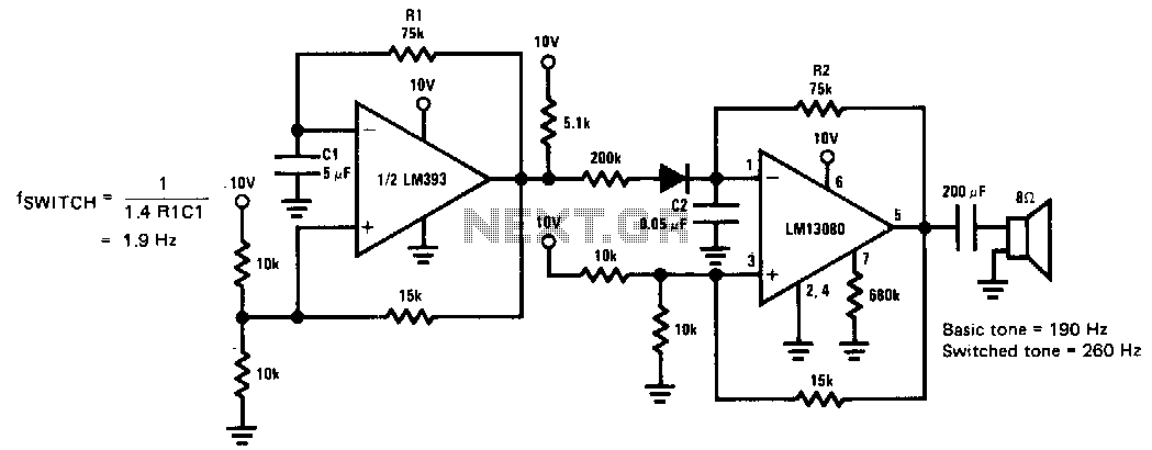
This siren provides a constant audio output while alternating between two distinct tones. The LM13080 is configured to oscillate at a fundamental frequency. This frequency can be modified by connecting a 200 kΩ charging resistor in parallel with the feedback resistor, R2.
The circuit operates using the LM13080, a versatile tone generator IC that is capable of producing audio tones through its internal oscillator. The fundamental frequency of the oscillation is determined by the values of the resistors and capacitors connected to the IC. In this configuration, a 200 kΩ resistor is added in parallel with the feedback resistor, R2, which influences the timing characteristics of the oscillator circuit.
The alternating tones generated by the siren can be achieved by modulating the output frequency. This modulation can be accomplished by adjusting the value of the feedback resistor, which affects the charge and discharge cycles of the timing capacitor. The result is a siren that alternates between two distinct audio frequencies, creating an effective alerting sound that can be used in various applications such as alarms, warning systems, and signaling devices.
To design the circuit, the following components are essential: the LM13080 IC, a timing capacitor (C1), the feedback resistor (R2), and the additional 200 kΩ charging resistor. The values of these components should be carefully selected to achieve the desired frequency range and tone alternation. The output can be connected to a speaker or buzzer that is capable of producing the audible tones at the specified frequencies.
In summary, the siren circuit utilizing the LM13080 IC is a practical solution for generating alternating tones, with the ability to adjust the frequency through resistor configuration, making it suitable for a variety of signaling applications.This siren provides a constant audio output, but alternates between two separate tones. The LM13080 is set to oscillate at one basic frequency; this frequency is changed by adding a 200-K!l charging resistor in parallel with the feedback resistor, R2. 🔗 External reference