
Two transistor AM radio receiver circuit
The two-transistor AM radio circuit operates by utilizing a simple design that effectively amplifies and demodulates amplitude-modulated radio signals. The circuit typically employs two NPN transistors, often identified as Q1 and Q2, which serve distinct roles in the overall functionality of the radio.
The first transistor, Q1, is configured as a radio frequency (RF) amplifier. Its primary function is to amplify the weak signals received by the antenna. The input to this stage is connected to an antenna, which captures AM radio waves. The amplified output from Q1 is then fed into the base of the second transistor, Q2.
Q2 is configured as a detector or demodulator. It extracts the audio signal from the amplified RF signal. This is accomplished through a simple diode detection method, where the audio frequency component is separated from the carrier wave. The output of Q2 is then coupled to a speaker or earphone, allowing the user to hear the audio content of the radio signal.
The passive components in the circuit include resistors, capacitors, and potentially an inductor, which are used for biasing the transistors, filtering, and tuning the circuit to the desired frequency. The simplicity of the design allows for easy construction on a breadboard or printed circuit board (PCB), making it accessible for hobbyists and educational purposes.
Overall, this two-transistor AM radio circuit exemplifies an efficient and straightforward approach to radio communication, demonstrating fundamental electronic principles while providing a functional radio receiver.This two transistor AM radio circuit is also called ""mini-radio"". It uses only 2 transistors and few passive components which makes is very easy to be cons.. 🔗 External reference
Related Circuits
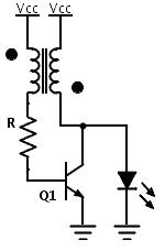
Previously, a boost circuit was tested that enables the powering of a 3 V LED using a discharged battery (approximately 1 V or lower). This circuit consists of a single transistor, one resistor, and a small transformer with a...
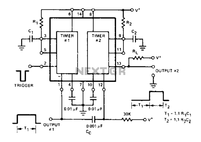
The Dual Timer Exar XR-2556 features a timing mechanism that can be triggered through capacitive coupling on a secondary timing pin. When a trigger input is engaged, the duration T1 can be set to 1.1R1C1, resulting in an increased...
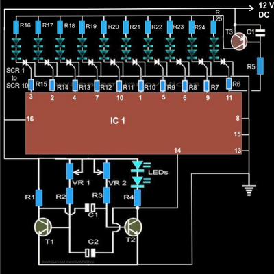
The article explains a straightforward method for creating an incremental LED bar graph using the IC 4017, which has specifications that may not fully align with current requirements. It discusses how to modify the IC for these operations. The...

This is a circuit design for a doorbell that produces a sound resembling that of a bird. The circuit is controlled by an NPN transistor. The operation begins when P1 is set to an experimental value, starting with approximately...
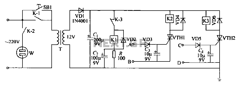
This schematic circuit features two alarm outputs controlled by a timer using thyristors. The system can be turned on or off and will shut down after the power supply is interrupted. It employs a transformer on the primary side...
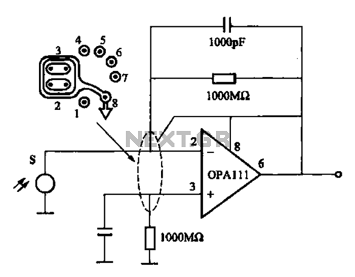
Infrared heat is emitted by an object during non-contact temperature measurement. The measured signal is weak, necessitating the use of highly sensitive thermal infrared sensors with minimal noise. Consequently, the amplifier circuit must also meet stringent requirements, as standard...