
Two-variable-led-matrix-display
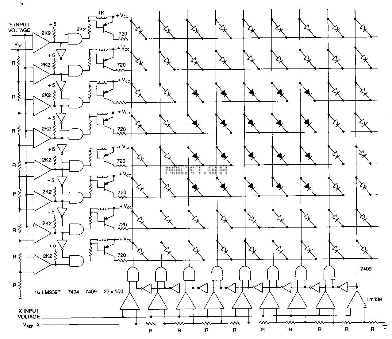
This matrix can display the values of two variables, such as frequency and voltage. The display consists of a graph made from a matrix of LEDs. The LEDs on each axis are color-coded: red indicates out of tolerance, while green signifies in tolerance, with a red band surrounding the inner green rectangle. The two input voltages, which are proportional to the functions being measured, are fed into two columns of comparators. The other input to the comparators is a reference voltage derived from a resistor ladder consisting of resistors R1 to Rx. The output from each row of comparators is processed through an inverter and an AND gate to ensure that only one output is active for any given input value. The LED at the intersection of the active drives indicates the relationship between the two inputs. The advantage of this display lies in its ease of reading, modification, and compact size. All comparators used are LM339 quad comparators.
The described matrix display circuit utilizes a two-dimensional LED array to visualize the relationship between two input variables, such as frequency and voltage. The matrix format allows for simultaneous monitoring of both parameters, enhancing the analysis of their interdependencies. The color-coding system employed in the LED display facilitates quick visual assessment of the input conditions: green LEDs indicate acceptable values, while red LEDs alert the user to out-of-tolerance conditions.
The design incorporates two columns of LM339 quad comparators. Each comparator column receives one of the input voltages, while the other input is a stable reference voltage generated from a resistor ladder network. This resistor ladder is composed of resistors R1 through Rx, providing a precise reference point against which the input voltages can be compared. The use of a resistor ladder allows for easy adjustment of the reference voltage by changing the resistor values, which can be beneficial for calibrating the system to different operational conditions.
The output from each row of comparators is processed by an inverter followed by an AND gate. This configuration ensures that only one LED will be activated for any specific combination of input values, preventing multiple LEDs from lighting up simultaneously, which could lead to confusion. The intersection of the active LED provides a clear indication of the relationship between the two inputs, allowing for immediate visual feedback.
The compact nature of the circuit, combined with its intuitive LED display, makes it suitable for applications where space is limited and quick visual feedback is essential. The use of LM339 comparators ensures reliable performance, given their low power consumption and high-speed operation, making this circuit an effective tool for monitoring and analyzing variable relationships in various electronic applications.This matrix can show the values of two variables, for example, frequency and voltage. The display is a graph made from a matrix of LEDs. The LEDs on each axis are color coded, red for out of tolerance and green for in, fanning a red band around the inner green rectangle. The two input voltages proportional to the functions being measured are presented to the two columns of comparators.
The other comparator input is a reference voltage derived from resistor ladder Rl to Rx. The output of each row of comparators is processed with an inverted and an AND gate to allow only one active output for any input value. The LED at the intersection of the active drives shows the relationship of the two inputs. The advantage of this display is the ease in reading, modification, and also its small size. All comparators are LM339 quads. 🔗 External reference