
UHF Wideband TV Amplifier for Signal

The UHF wideband signal amplifier is designed to enhance weak television signals, particularly in the UHF frequency range of 400 to 850 MHz. The amplifier's gain, specified between 10 and 15 dB, is critical for improving signal strength, which is especially beneficial in areas with poor reception.
The construction of the amplifier involves careful attention to the physical layout of the components. Surface-mounted devices (SMDs) such as capacitors C1, C2, C6, and C7 should be mounted with minimal lead length to reduce parasitic inductance and capacitance, which can adversely affect performance. The metal enclosure not only protects the circuitry but also serves to shield the amplifier from electromagnetic interference (EMI), enhancing overall signal integrity.
Powering the amplifier requires a stabilized 12V source, which ensures consistent operation. The use of a coaxial cable for the connection from the antenna to the amplifier is standard practice, as it minimizes signal loss and provides a robust connection. The introduction of a 10 - 100 µH inductor in the power line is essential for filtering out noise from the power supply, thereby improving the amplifier's performance.
The coupling capacitor serves to isolate the amplifier from the television set while allowing the amplified signal to pass through. This design choice prevents any DC voltage present in the amplifier from affecting the TV circuitry.
Adjustment of the amplifier is simplified with the inclusion of potentiometer P1. Setting P1 to the midpoint allows for a baseline configuration, from which fine-tuning can be performed to optimize the image quality. This user-friendly adjustment mechanism is crucial for achieving the best possible performance in varying signal conditions, ensuring that users can easily adapt the amplifier to their specific environment.
In summary, the UHF wideband signal amplifier is a vital component for enhancing weak television signals, and its design incorporates several key features that ensure optimal performance and ease of use.This UHF wideband signal amplifier has a total gain of 10 to 15 dB in the 400 - 850 MHz domain frequency so it can be used where the tv signal is weak. For UHF TV signal amplifier to work correctly, you need to cut the components pins as short as possible.
C1, C2, C6, C7 are SMD type (surface mounted). This antenna tv amplifier or uhf wideband amp lifier need to be build inside of a metal box and then connected close to the tv antenna. The power supply is a simple 12V stabilized source. The tv antenna amplifier can be connected directly to the power supply thru coaxial cable of the tv antenna but you need a 10 - 100uH coil on the alimentation line. The tv set will be connected to the uhf amplifier thru a small coupling capacitor. Adjusting is easy, just bring the P1 to the middle and then adjust it untill you obtain the best tv image quality.
🔗 External reference
Related Circuits
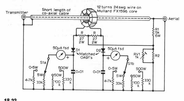
The power amplifier (PA) output Pi section features two variable capacitors: one ranging from 20 to 120 pF and a second, custom-built capacitor with a range of 50 to 450 pF. The latter is activated for lower frequency bands...
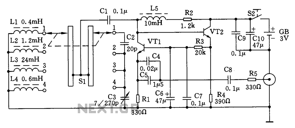
This is a simple high-frequency signal generator. By changing the inductance of the LC resonant circuit using the band switch S1, the high-frequency oscillation frequency range can be altered. The generator is divided into four frequency stages: the first...
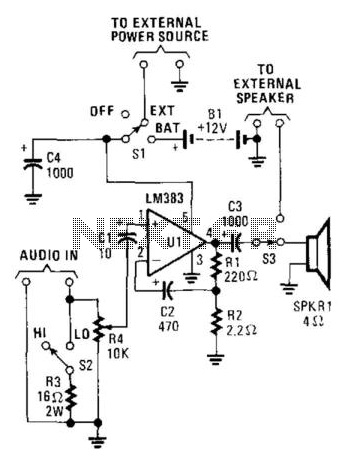
This audio power amplifier, built around an LM383 8-W audio power amplifier, is designed to enhance an audio signal to a sufficient level for audibility in high-noise environments. It is important to note that the LM383 requires a heatsink...
This document presents a schematic diagram of an electret microphone pre-amplifier utilizing the LMV721 operational amplifier. The LMV721 is chosen for its low noise and low power characteristics. The electret microphone pre-amplifier circuit is designed to amplify the weak audio...
To complement the 60 Watt MOSFET audio amplifier, a high-quality preamplifier design was necessary. A discrete components topology utilizing ±24V supply rails was selected, with an emphasis on minimizing the transistor count while achieving low noise, very low distortion,...
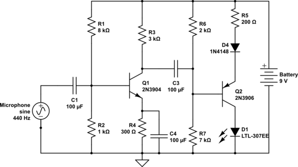
The circuit takes input from a microphone to power an LED, which remains off in ambient sound conditions and brightens with increasing noise levels. The peak voltage produced by the microphone is proportional to the sound levels. The microphone...
Warning: include(partials/cookie-banner.php): Failed to open stream: Permission denied in /var/www/html/nextgr/view-circuit.php on line 713
Warning: include(): Failed opening 'partials/cookie-banner.php' for inclusion (include_path='.:/usr/share/php') in /var/www/html/nextgr/view-circuit.php on line 713