
Ultra-precision-instrumentation-amplifier
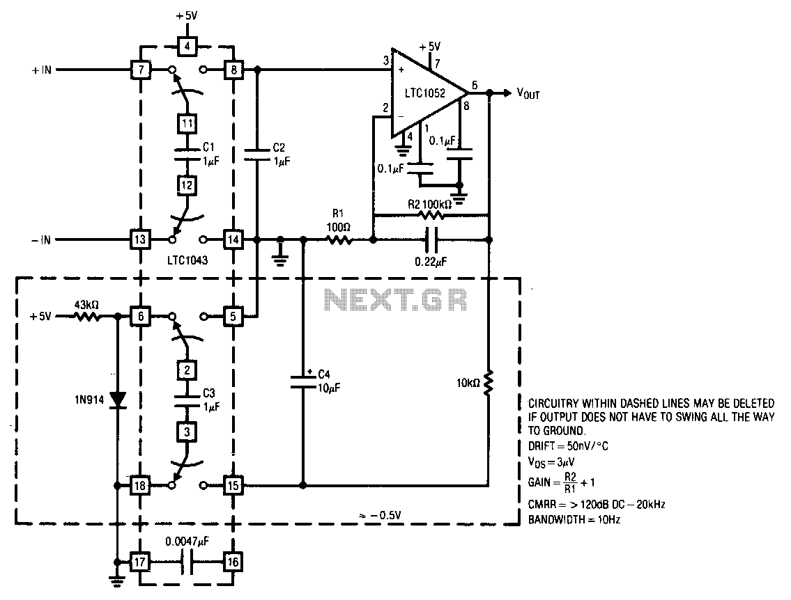
This circuit operates from a single 5 V power supply. The LTC1043 switched-capacitor instrumentation building block facilitates a differential-to-single-ended transition using a flying-capacitor technique. The circuit alternately samples the differential input signal and charges the ground-referred capacitor C2 with this information. The LTC1052 measures the voltage across C2 and provides the circuit's output. The gain is determined by the ratio of the amplifier's feedback resistors. Typically, the LTC1052's output stage can swing within 15 mV of ground. If operation down to zero is necessary, the circuit shown in dashed lines can be implemented. This configuration utilizes the remaining section of the LTC1043 to generate a small negative voltage by inverting the diode drop. This potential drives the 10 kΩ pull-down resistor, ensuring the LTC1052's output operates in class A mode for voltages near zero. It is important to note that the circuit's switched-capacitor front-end acts as a sampled-data filter, maintaining a high common-mode rejection ratio even at increasing frequencies. The 0.0047 µF capacitor sets the front-end switching frequency at a few hundred Hz.
The circuit is designed for applications requiring precise signal conditioning from differential inputs to single-ended outputs, suitable for low-voltage environments. The LTC1043's switched-capacitor architecture allows for effective signal processing by utilizing capacitive charge transfer, which enhances the circuit's performance by minimizing noise and distortion. The differential-to-single-ended conversion is critical in applications where differential signals must be processed or interfaced with single-ended systems.
The LTC1052 operational amplifier is pivotal in this design, providing the necessary gain and output characteristics. The selection of feedback resistors directly affects the gain, allowing for flexibility in the circuit's response based on application needs. The ability of the LTC1052 to operate close to ground potential is particularly advantageous in low-voltage applications, ensuring that the output can accurately reflect small signal variations near zero volts.
For applications that demand operation down to zero volts, the additional configuration utilizing the LTC1043 to create a negative voltage is a significant enhancement. This modification ensures that the output can maintain class A operation, which is essential for linear performance in low-signal conditions. The use of a pull-down resistor further stabilizes the output, preventing unwanted fluctuations that could arise from low-voltage operation.
The circuit's design also incorporates a sampled-data filter through the switched-capacitor front-end, which is crucial for maintaining high common-mode rejection ratios. This characteristic is particularly important in environments with high levels of electromagnetic interference or noise, as it ensures that the desired signal remains intact while rejecting common-mode noise. The choice of a 0.0047 µF capacitor for setting the switching frequency at a few hundred Hz indicates a balance between speed and stability, allowing the circuit to effectively process signals without introducing significant phase shifts or delays.
Overall, this circuit is well-suited for precision measurement applications, sensor interfacing, and signal conditioning tasks where maintaining signal integrity in low-voltage scenarios is critical.This circuit will run from a single 5 V power supply. The LTC1043 switched-capacitor instrumentation building block provides a differential-to-single-ended transition using a flying-capacitor technique. Cl alternately samples the differential input signal and charges ground referred C2 with this information.
The LTC1052 measures the voltage across C2 and provides the circuit"s output. Gain is set by the ratio of the amplifier"s feedback resistors. Normally, the LTC1052"s output stage can swing within 15 mV of ground. If operation all the way to zero is required, the circuit shown in dashed lines can be employed. This configuration uses the remaining LTC1043 section to generate a small negative voltage by inverting the diode drop. This potential drives the 10-KO, pull-down resistor, forcing the LTC1052"s output into class A operation for voltages near zero.
Note that the circuit"s switched-capacitor front-end forms a sampled-data filter allowing the common-mode rejection ratio to remain high, even with increasing frequency. The 0.0047uF unit sets front-end switching frequency at a few hundred Hz. 🔗 External reference