
Ultrasonic Drilling Machine Two
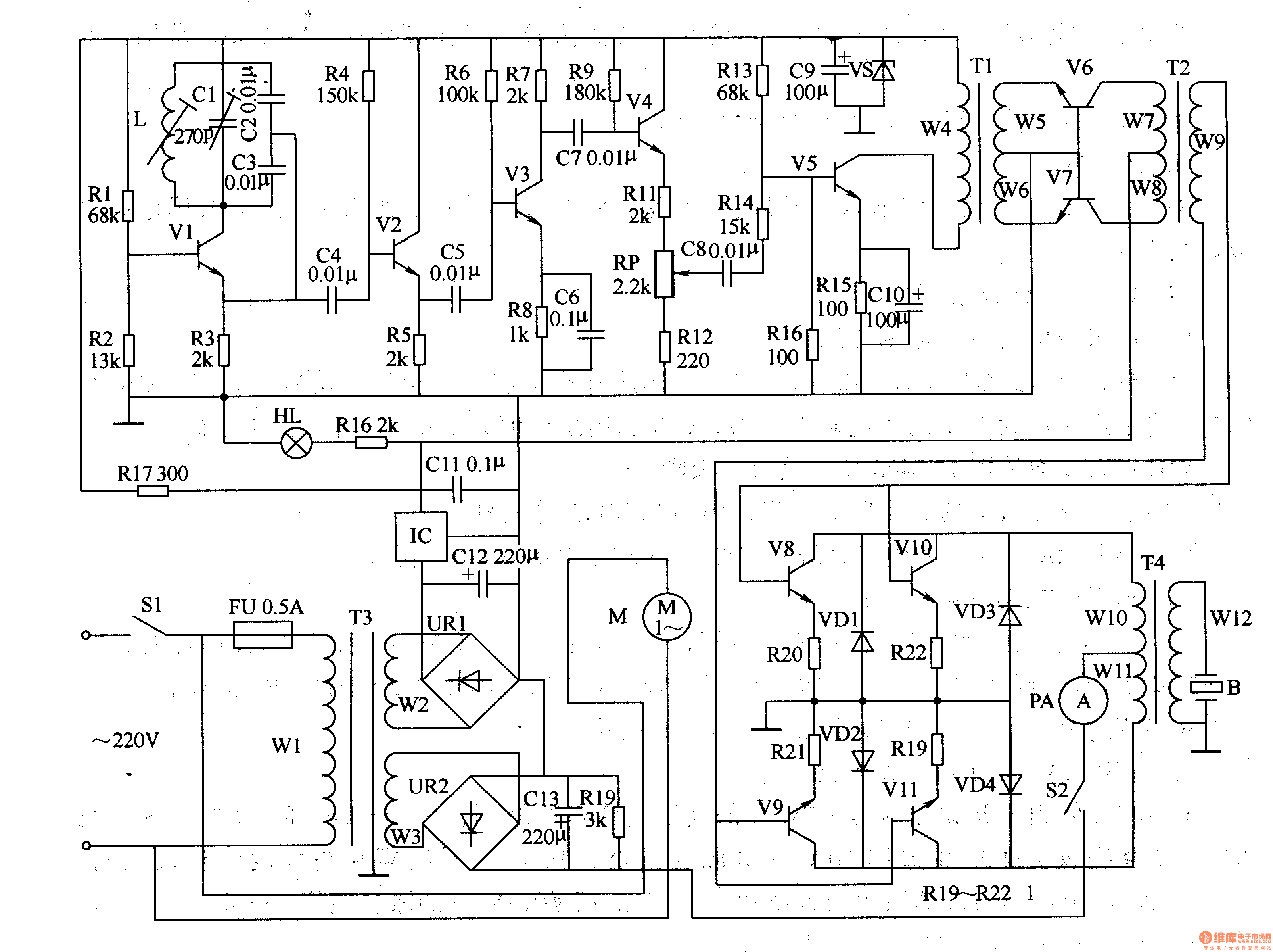
The power supply section begins with the power switch (S1), which controls the flow of electricity to the circuit. Following the switch, the fuse (FU) provides protection against overcurrent conditions, ensuring that the circuit components remain safe from damage. The power transformer (T1) steps down the AC voltage to a suitable level for the circuit's operation.
The bridge rectifier, consisting of diodes (UR1 and UR2), converts the AC voltage from the transformer into a pulsating DC voltage. This DC voltage is then smoothed by the capacitors (C9 and C11-C13), which filter out the ripples, providing a stable DC supply to the subsequent stages of the circuit.
The ultrasonic oscillator circuit generates high-frequency signals necessary for ultrasonic applications. This signal is first amplified by the pre-amplifier, which boosts the weak signals from the oscillator. The amplifier further increases the signal strength before it reaches the power amplifier, which drives the output circuit. The power amplifier ensures that the output signal is strong enough to drive the load, which may be an ultrasonic transducer or another device requiring high-frequency signals.
Resistors (R16 and R17) are used within the circuit for biasing and setting gain levels in the amplifier stages, contributing to the overall performance and stability of the circuit. Each component plays a critical role in ensuring that the circuit functions effectively for its intended application, which may include ultrasonic cleaning, sensing, or other ultrasonic technologies.Work of the circuit The circuit consists of power supply circuit, ultrasonic oscillator circuit, pre-amplifier, amplifier and power amplifier drive output circuit. (It is showed in picture 8-125.)Power supply circuit consists of power switch Sl, fuse FU, power transformer m, bridge rectifier, URl and UR2, capacitors C9 and Cll-C13, resistors R16 and R17, v..
🔗 External reference
Related Circuits
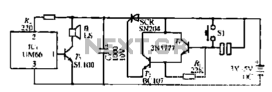
A few custom integrated circuits began to play music. When the song ends, no electricity flows through the thyristor, which then cuts off the light, causing the phototransistor to activate. The system is designed with a touchpad; each touch...
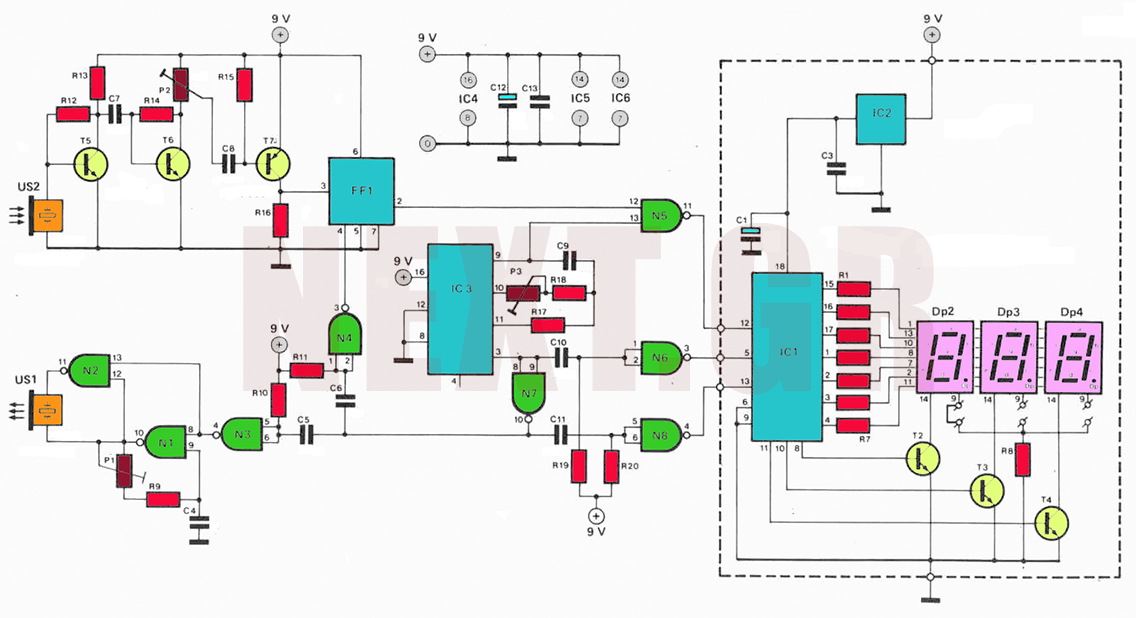
The circuit utilizes ultrasonic oscillations to measure the distance between two points based on the speed of sound in air. By measuring the time it takes for the ultrasonic wave to travel between these points, the distance can be...
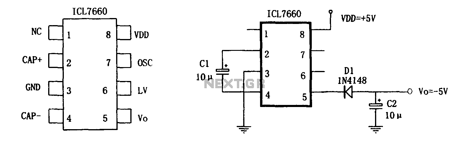
The circuit consists of two capacitors arranged as indicated by the ICL7660, which is utilized for external power conversion. The power supply employs the dedicated integrated circuit ICL7660 for polarity inversion and external charge pump capacitors, forming a DC/DC...
The following circuit illustrates an Ultrasonic Sensor Circuit Diagram. This circuit is based on the MAX232 IC. Features include a quiescent current of 150mA. The Ultrasonic Sensor Circuit utilizes the MAX232 integrated circuit, which is primarily designed for converting signals...
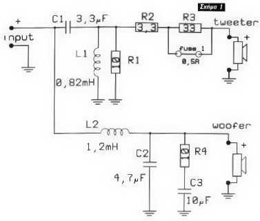
The resistance of loudspeakers is characterized in a frequency depending on the destination and their press. Loudspeakers are distinguished, as for the destination, in loudspeakers of low frequencies, woofer intermediate, mid-range and high tweeter. Their resistance in Ω is...
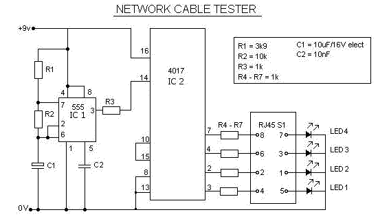
This is a multifunction RJ45 network cable tester designed for testing network cables (RJ45) and telephone cables (RJ11). It is cost-effective and user-friendly. The tester determines whether a network cable is a crossover or straight type by illuminating a...