
Ultrasonic-pest-repeller
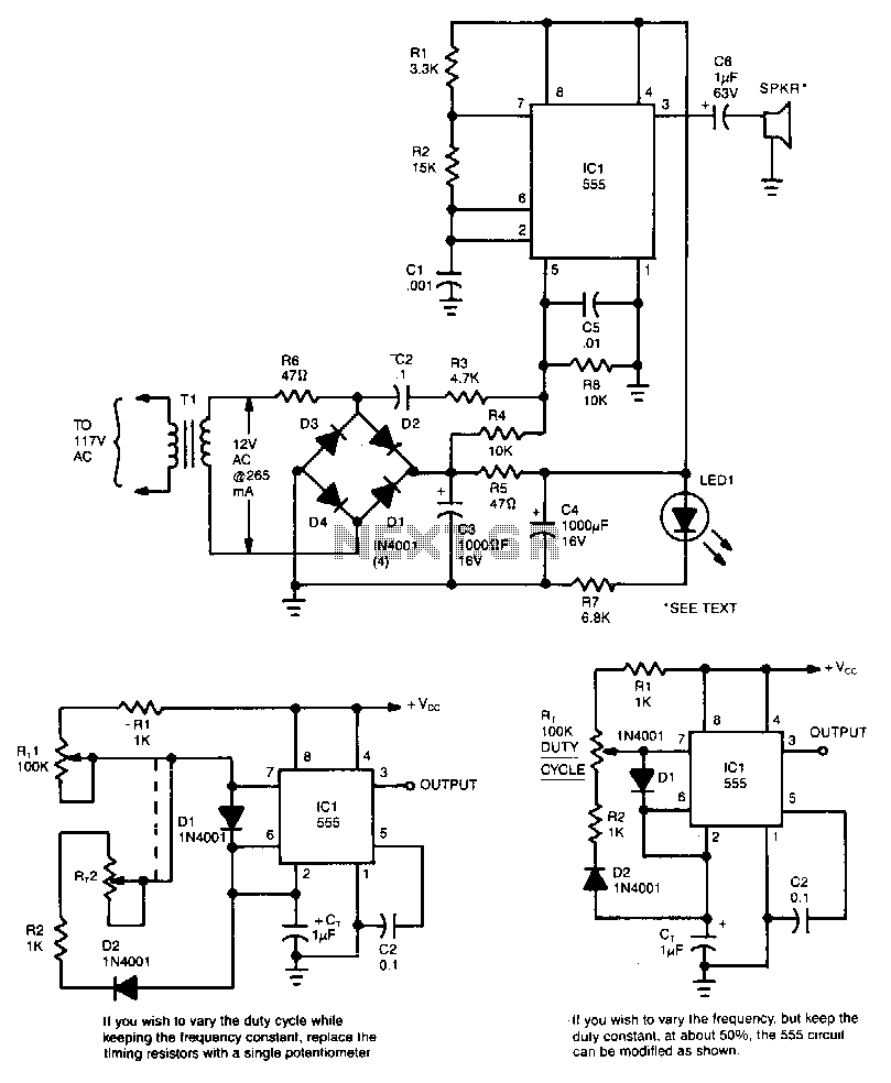
This circuit utilizes a 555 timer integrated circuit (IC) configured as a square-wave generator. The base frequency is approximately 45 kHz, determined by the resistor values R1, R2, and the capacitor C1. The 45 kHz carrier frequency is frequency modulated by a modified trapezoidal voltage waveform applied to pin 5 of the 555 timer. This modulating voltage is generated by a network comprising C2, R3, and R4, which are connected across one leg of a bridge rectifier. The modulation sweep extends approximately 20 kHz on either side of the base frequency. The output is directed to a 2-inch piezoelectric tweeter speaker.
The circuit employs a 555 timer IC, which is a versatile and widely used device in various timing applications. In this configuration, it operates in astable mode, producing a continuous output square wave. The frequency of oscillation is primarily influenced by the resistors R1 and R2, along with the capacitor C1, which sets the timing intervals for the high and low states of the output.
The modulation of the base frequency is achieved through the application of a trapezoidal waveform to pin 5, which is the control voltage input of the 555 timer. The trapezoidal waveform alters the timing characteristics of the output signal, effectively varying the frequency around the base frequency of 45 kHz. The components C2, R3, and R4 form a voltage divider and filter network that shapes the trapezoidal waveform, allowing for smooth frequency modulation.
The bridge rectifier serves to convert any alternating current (AC) input into direct current (DC), which is necessary for the operation of the 555 timer. The output from the 555 timer drives a 2-inch piezoelectric tweeter speaker, which converts the electrical signals into audible sound. The piezoelectric tweeter is capable of producing sound across a range of frequencies, making it suitable for applications requiring sound generation from modulated signals.
Overall, this circuit design effectively combines frequency generation and modulation techniques to produce a variable audio output, demonstrating the utility of the 555 timer IC in audio applications.This circuit is a 555 timer IC connected as a square-wave generator. Its base frequency is approximately 45kHz, as detennined by the values of Rl, R2, and Cl. The 45-kHz carrier is frequency modulated by a modified trapizoidal voltage waveform applied to pin 5 of the 555 timer. That modulating voltage is developed by a network consisting of C2, R3, and R4 connected across one leg of the bridge rectifier.
The sweep is approximately 20kHz on each side of the base frequency. The speaker is a 2-inch piezoelectric tweeter. 🔗 External reference