
Ultrasonic-pulsed-pest-controller
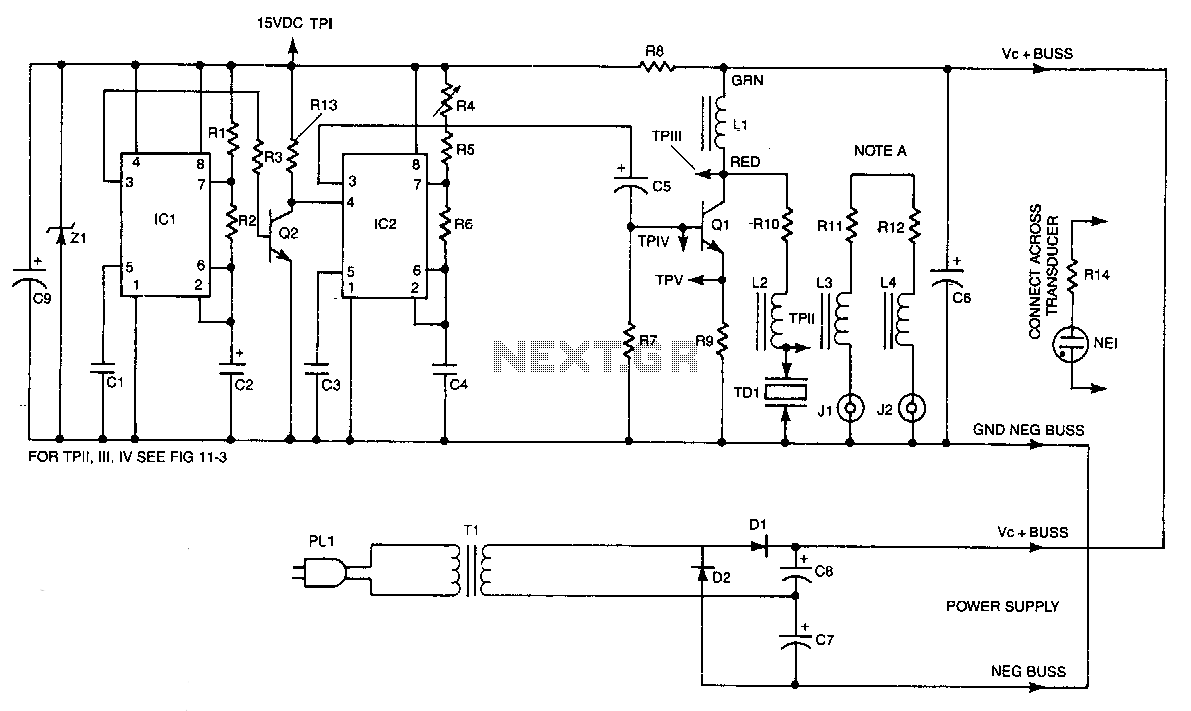
IC2 is a stable oscillator whose frequency and pulse width are determined by the values of R4, R5, R6, and C4. R4 is adjustable for precise frequency setting. The output from IC2 is at pin 3, which is capacitively coupled to the base of Q1. L1 acts as a high-impedance choke to the signal while allowing the collector of Q1 to be de-biased. Q1 amplifies the positive pulses from IC2 and drives the series resonant combination of L2 and TD1. Resistor R10 broadens the response of this resonant circuit. L2 and the inherent capacitance of the transducer, TD1, form a resonant circuit at approximately 23 kHz. It is typically found that most rodents are disturbed when the signal is pulsed with the off time exceeding the on time. This timing is controlled by timer IC1 and timer inverter Q2. IC1 operates in a free-running mode, with its periods determined by R1, R2, and C2, resulting in approximately two seconds off and two seconds on. The periods are inverted via Q2 and used to gate pin 4 of IC2, the frequency oscillator, turning it on for two seconds and off for three seconds. The power supply consists of a conventional voltage doubler with a Zener regulator for the oscillator voltages.
IC2 serves as the core component of a frequency modulation circuit designed for pest deterrent applications. The oscillator's frequency is finely tunable through the adjustable resistor R4, allowing for precise control over the output frequency. The output signal from IC2 is taken from pin 3 and is coupled to the base of the transistor Q1 through a capacitor, ensuring that only AC components pass through, thus protecting the transistor from any DC bias that could affect its operation.
Inductor L1 is strategically placed to function as a high-impedance choke, effectively isolating the signal path while maintaining the necessary biasing conditions for Q1. The transistor Q1 is pivotal in amplifying the signal generated by IC2, transforming the low-level oscillations into a more robust drive signal suitable for the resonant circuit formed by L2 and the transducer TD1.
The resonant circuit, composed of L2 and the inherent capacitance of TD1, is tuned to resonate around 23 kHz, a frequency that has been shown to be particularly effective in deterring rodents. The use of resistor R10 enhances the bandwidth of this resonant circuit, allowing for a broader range of frequencies to be effective in disrupting rodent behavior.
The timing of the signal is managed by timer IC1, which operates in a free-running mode. The timing components R1, R2, and C2 define the duty cycle, resulting in a signal that is on for approximately two seconds and off for two seconds. This cycle is inverted by Q2, which gates the frequency oscillator IC2, enabling it to operate for two seconds and then remain off for three seconds. This pulsing method is critical in creating an effective deterrent signal, as it mimics natural disturbances that can be unsettling to rodents.
The power supply for the circuit is designed as a voltage doubler, providing the necessary voltage levels for the oscillator's operation. A Zener regulator is employed to ensure stable voltage levels, safeguarding the oscillator and other components from voltage fluctuations that could impair performance. This comprehensive design ensures optimal functionality and reliability of the pest deterrent system.IC2 forms a stable oscillator whose frequency and pulse width is determined by the values of R4, R5, R6, and C4. R4 is made adjustable for precise frequency setting. The output of IC2 is pin 3, which is capacitively coupled to the base of Ql. Ll acts as a high-impedance choke to the signal, while allowing the collector of Ql to be de-biased.
Ql amplifies the positive pulses from IC2 and step drives the series resonant combination ofL2 and TDl. Resistor RlO serves to broaden the response of this resonant circuit. L2 and the inherent capacity of the transducer, TDl, forms a resonant circuit at around 23kHz. It is usually found that most rodents are bothered when the signal is pulsed with the off exceeding the on time. This timing is accomplished via timer ICl and timer inverter Q2. ICl is free running and its periods are determined by Rl, R2, and C2 to be approximately two seconds off and two seconds on.
The periods are inverted via Q2 and used to gate pin 4 of IC2, the freqoency oscillator, turning it on for two seconds and off for three seconds. The power supply is a conventional voltage doubler with a zener regulator for the oscillator voltages.
🔗 External reference