
Ultrasonic Reflectance Detector
This motion detection circuit is designed to operate effectively within a limited range of approximately 5 inches, utilizing a single piezo-ceramic ultrasonic transducer (X1) operating at a frequency of 40 kHz. The circuit employs a square-wave astable multivibrator (U1) to drive the transducer, which is tuned to its resonance using a variable resistor (RV1). The emitted ultrasonic waves are monitored for reflections caused by nearby obstructions, which alters the vibration of the transducer and thus affects the AC signal voltage received at the input of an operational amplifier (U2A).
The signal processing begins with U2A, configured as a unity-gain buffer that relays the AC voltage to a half-wave rectifier (CR1). The rectifier is biased to clamp the lower portion of the waveform, allowing only the upper part to be averaged through a resistor-capacitor network (R6 and C5). This averaged signal represents the detected level correlated with the ultrasonic emissions from X1.
Subsequently, the amplified signal is processed by another operational amplifier stage (U2B), which increases the signal amplitude by a factor of approximately 100. The output from U2B is further averaged before being fed into the negative input of another operational amplifier (U3A). This stage functions as an AC comparator, comparing the amplified signal against a reference voltage derived from the averaged input.
Upon detecting motion, U3A's output transitions high, initiating the charging of a capacitor (C10) through a diode (CR2) and resistor (R12). The discharge of C10 occurs gradually through resistor R13 when motion ceases. The voltage across C10 triggers a hysteretic NAND gate (U4A) configured as an astable multivibrator, producing a square wave output at approximately 10 Hz. This output is then used to activate another astable multivibrator (U4C), generating an audible tone at around 1 kHz that is output through an audio sounder (X2).
The circuit is powered by a low-dropout voltage regulator (VR1) designed for 9V battery operation, although alternative solutions for providing regulated 7V can be implemented due to the discontinuation of the original component. The overall current draw is approximately 3 mA, with suggestions for further power efficiency improvements by utilizing ultra-low power components. The circuit's design ensures resilience against ambient noise, making it suitable for various applications where false triggering due to environmental sounds might otherwise occur. A settling time of about 10 seconds is required after power-up to ensure reliable detection capabilities.This circuit detects motion within approximately 5 inches of a piezo-ceramic element ultrasonic transducer. The detection distance is much smaller than obtainable with other ultrasonic techniques, however, it only requires a single transducer, as opposed to the two-transducer arrangement typically found in other designs.
The short-range detection is adequate for many applications, such as proximity-operated commodity dispensers or tamper alarms for merchandise cases. X1 is a directional, piezo-ceramic element, 40kHz ultrasonic transducer driven via R2 by U1, a square-wave astable multivibrator.
U1 is tuned to X1`s resonance with RV1. X1 emits ultrasonic energy from its aperture. When X1`s aperture is unobstructed, the AC signal voltage at U2A pin 3 remains constant. Introducing an obstruction near the aperture causes some of the ultrasonic radiation to reflect back into X1`s element, affecting the element`s vibration. This causes a disturbance in the amplitude of the signal voltage, as the reflected energy either cancels or reinforces X1`s emission.
U2A is configured as a unity-gain buffer, providing the signal voltage to a half-wave rectifier, CR1, via R3. The anode of CR1 is biased via R4 and R5 so that the lower portion of the signal voltage waveform is clamped.
C4 provides a low impedance for the bias. The upper part of the waveform is averaged by R6 and C5. The voltage at the junction of R6 and C5, therefore, is the detected level corresponding to the voltage at X1. U2B, in association with R7, R8, C6 and C7, multiplies the detected level by an AC gain of about 100.
The AC-amplified signal appears at U2B`s output, and is further averaged by the long-time constant of R11 and C8. The averaged level is provided to the negative input of op amp U3A. The AC-amplified signal is also provided to U3A`s positive input, scaled slightly by R9 and R10. U3A performs the function of an AC comparator, where the reference is established by the averaged voltage at its negative input.
The scaling provided at U3A`s positive input prevents the stage from producing an erratic output when no motion is present. When motion is present, U3A`s output goes high, quickly charging C10 via CR2 and R12. When motion ceases, C10 is slowly discharged by R13. U4A is a hysteretic (Schmitt) 2-input NAND gate configured as an astable multivibrator. When the voltage at C10 becomes sufficiently high to reach the threshold value of U4A`s pin 1, it begins to oscillate at approximately 10 Hertz.
The 10 Hertz square wave subsequently keys U4C, a second astable multivibrator with an audible frequency of about 1kHz. U4B provides logic inversion so that U4C is activated with motion. U4C`s output drives one side of audio sounder X2, while U4D drives the sounder`s other side with a complimentary waveform.
The combined functions of the four NAND gates produces a pulsating tone in X2 when motion occurs. VR1 is a low-dropout, low ground-current regulator ideal for use with 9v batteries. At this writing, Panasonic unfortunately stopped manufacturing this part, and there is no known direct replacement. However, any means of providing regulated 7v to the circuit may be used. Current consumption is about 3mA, with about 750uA used by U1, and 200uA wasted in U3B, an unused op amp section.
A reduction in current may be immediately realized by replacing dual op-amp U3 with an ultra-low power comparator such as Texas Instruments type TLV3701IP. Lower-current substitutes for U1`s function may also be possible. This circuit exhibits exceptionally good immunity to ambient acoustic interference, and may therefore be used in noisy environments without false-triggering.
Overall power reduction by means of intermittent power application is possible, however, the circuit`s various time constants require a settling interval of about 10 seconds after application of the supply voltage, before accurate detection can occur. 🔗 External reference
Related Circuits
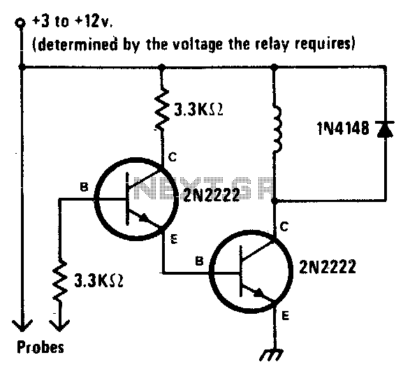
This is a straightforward liquid detector that utilizes a relay to activate an evacuation mechanism. It can be employed for water or any liquid that conducts electricity. Any PNP transistor capable of handling the relay current can be used....
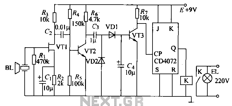
The T-40-16 and 555 ultrasonic transmitter circuit configuration consists of an ultrasonic transmitter T-40-16 and a 555 timer circuit. By adjusting the potentiometer RP, the oscillation frequency of the circuit can be changed. The output pulse frequency from the...
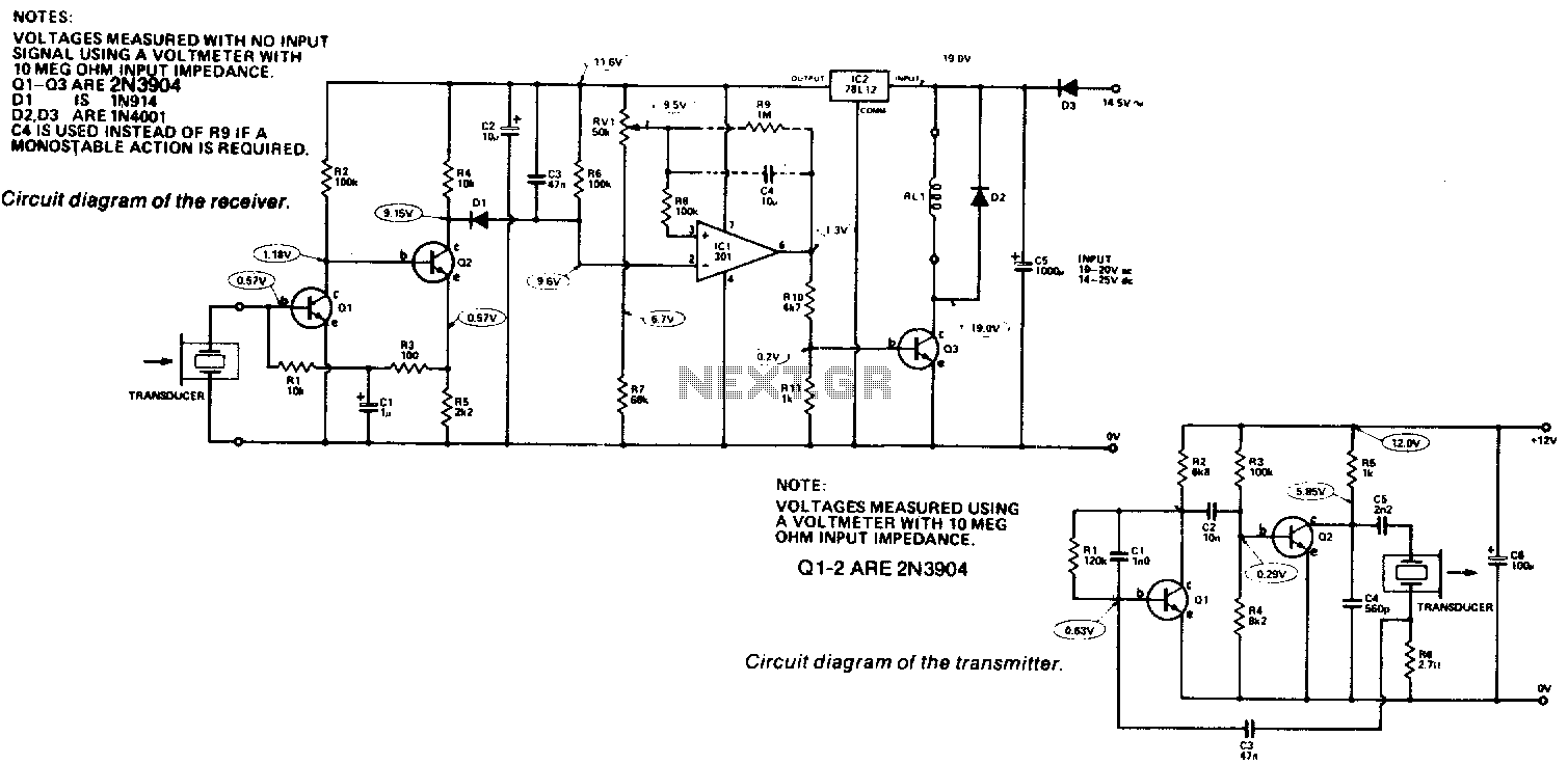
Receiver. The output from the transducer is amplified by Q1 and Q2, and rectified by D1. The voltage on pin 2 of IC1 will become more negative as the input signal increases. IC1 is utilized as a comparator, comparing...
A circuit designed to extract and measure the modulated carrier of an infrared remote control. This circuit amplifies the entire received signal, allowing the waveform to be displayed on an oscilloscope or a frequency counter. It can measure modulation...
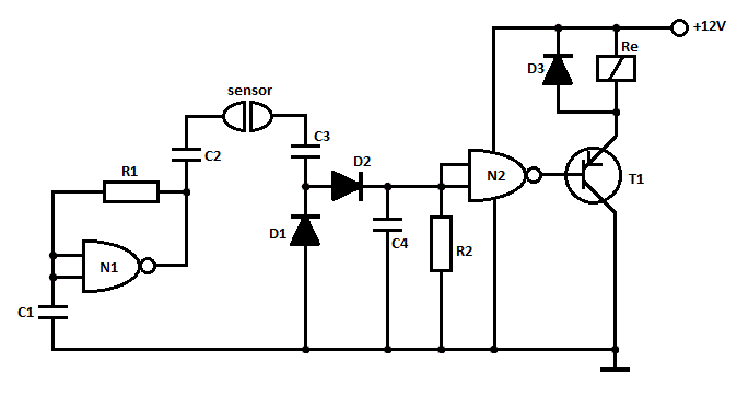
A gas leak detector circuit that detects the leakage of LPG gas and alerts the user through audio-visual indications. The circuit operates off a 9V PP3 battery. A Zener diode is used to convert 9V into 5V DC to...
When the liquid level reaches both probes, the alarm is activated. When the water level recedes, the alarm is deactivated. The described circuit functions as a liquid level monitoring system utilizing two probes to detect the presence of liquid. The...