
Understanding the Music Man Stingray 2-band preamp
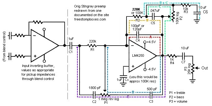
The Music Man Stingray bass guitar preamp circuit is designed to amplify the low-level signals generated by the guitar's pickups. The preamp typically consists of several key components, including operational amplifiers, resistors, capacitors, and a power supply input. The choice of a 9V DC power supply is common in many audio applications, providing a balance between adequate headroom and low noise.
At the input stage, the preamp circuit typically includes a high-impedance buffer to ensure that the signal from the guitar pickups is not loaded down. This is often implemented using an operational amplifier configured as a non-inverting amplifier. The gain of this stage can be adjusted by selecting appropriate feedback and input resistors.
Following the input stage, additional filtering capacitors may be included to remove unwanted high-frequency noise and to stabilize the power supply. The circuit may also feature tone control elements, such as passive RC networks, allowing the user to adjust bass, midrange, and treble frequencies according to personal preference.
The output stage of the preamp is designed to drive the subsequent amplification stages or effects pedals. This stage may also utilize an operational amplifier to ensure that the output signal maintains a low output impedance, facilitating better signal transfer to the next stage in the audio chain.
In summary, the schematic for the Music Man Stingray bass guitar preamp illustrates a well-thought-out design that emphasizes signal integrity, user control over tonal characteristics, and compatibility with standard audio equipment. The omission of the voltage divider section suggests a focus on simplifying the schematic for clarity, while still retaining the essential functionality of the preamp circuit.The schematic here is of the original Music Man Stingray bass guitar preamp. It runs off 9VDC and I have left off the voltage divider part of the.. 🔗 External reference
Related Circuits
This is a collection of phono (black vinyl for the youngsters) preamps and equalisation circuits, one of which is sure to meet your requirements. These are not my circuits, but were contributed by a reader, so I am not...
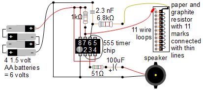
A simple music instrument/keyboard is created using a 555 timer chip circuit, a piece of paper, and a pencil. The project includes a more advanced automatic music player that utilizes a playing head and a long sheet of paper...
The circuit design utilizes a VHF amplifier configured to operate within the frequency range of 88 to 108 MHz, specifically for Band 2 radio applications. The VHF amplifier circuit is designed to enhance weak radio frequency signals in the specified...
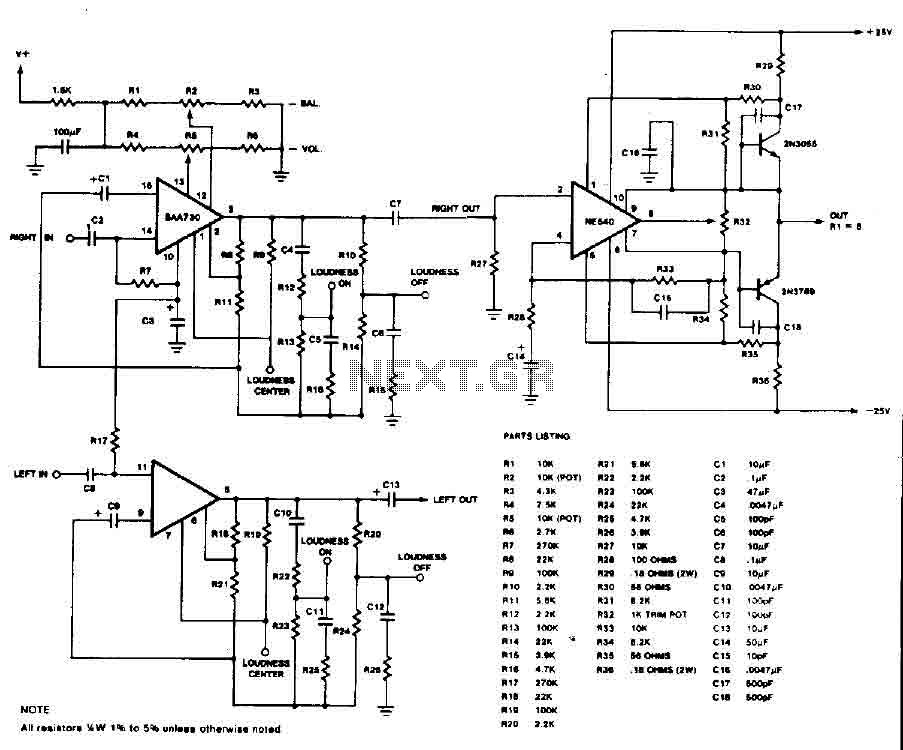
This circuit is an audio preamplifier that has balance, tone, and loudness controls. It should be suitable as an example of good design for audio applications. The audio preamplifier circuit utilizes the BAA730 and NE540 integrated circuits, which are...
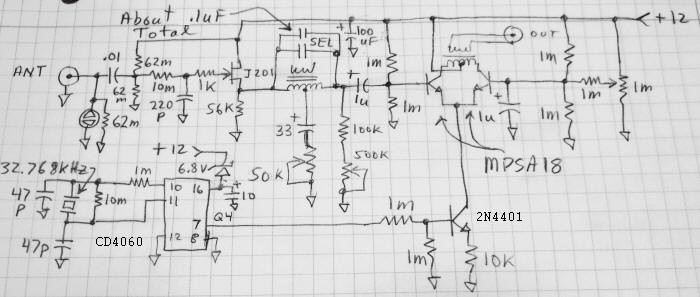
Using a circuit similar to the LF block converter, a Schumann Resonance Converter has been developed to shift near-DC signals up to approximately 2 kHz for compatibility with a standard soundcard. The initial test results indicate successful operation, with...
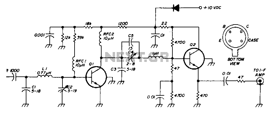
The low-noise preamplifier features a noise figure of 1 dB at 30 MHz and a 3 dB bandwidth of 10 MHz. The gain is 19 dB. The total current drain with a +10 volt supply is 13 mA. The...
Warning: include(partials/cookie-banner.php): Failed to open stream: Permission denied in /var/www/html/nextgr/view-circuit.php on line 713
Warning: include(): Failed opening 'partials/cookie-banner.php' for inclusion (include_path='.:/usr/share/php') in /var/www/html/nextgr/view-circuit.php on line 713