
Undervoltage lockout for small-power MOSFET gate driver
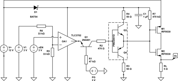
The battery switch-over circuit is designed to ensure seamless transition between two power sources while maintaining a stable output voltage. The circuit employs two lanes, each featuring a pair of p-MOSFETs configured in a back-to-back arrangement. This configuration allows for effective isolation and switching between the two battery sources, thus preventing reverse current flow and ensuring that only one battery is connected to the load at any given time.
The operational voltage range of 3V to 12V provides flexibility for various applications, making the circuit suitable for use in battery-powered devices. The logic control, although not detailed in the schematic, is critical for determining which lane is enabled based on the voltage levels of the connected batteries. This logic could be implemented using a microcontroller or dedicated logic circuitry that monitors the battery voltages and activates the appropriate lane.
Powering the switch-over circuitry and drivers through Vs, which is derived from the combined output of the batteries via diodes, allows for efficient utilization of the available battery power. However, careful consideration must be given to the scenario where Vs falls below 3V. At this threshold, the voltage approaches the safe operating limit for the gate of the p-MOSFETs, which is calculated as twice the gate threshold voltage (2 x Vg, th = 3V). Additionally, the TLC3702 comparator, which is likely used for voltage monitoring or control, has a minimum operating voltage that must not be exceeded to ensure reliable performance.
To mitigate potential issues arising from low Vs conditions, it may be beneficial to implement additional circuitry that monitors the voltage and provides feedback to the logic control. This could involve using a voltage divider or a dedicated voltage supervisor IC that can trigger a switch-off or lane change before the voltage drops to critical levels. By incorporating these features, the reliability and efficiency of the battery switch-over circuit can be enhanced, ensuring consistent operation across its specified voltage range.Developing a battery switch-over circuit which is made of two lanes of the depicted circuit. Operation voltage range is from 3V. 12V. Only one lane should be enabled at a time which is governed by logic not included in the schematic. Each lane can (dis)connect its battery (V+) by means of two back-to-back p-MOSFETs (Vg, th = 1. 5V). The drivers and switch-over circuitry are powered by Vs which is derived by OR-ing all batteries via diodes. Now I am concerned over the case when the Vs voltage falls below around 3V which comes close to the MOSFETs safe (2x Vg, th) gate threshold voltage and the TLC3702 comparator minimum operating voltage. 🔗 External reference
Related Circuits
Touch screens are increasingly popular, yet many developers have never designed one. This guide provides a step-by-step approach to the necessary hardware and software for successful touch screen implementation. Touch screens are ubiquitous in industrial control systems, consumer electronics,...
Posts about a tutorial written by Harandi and Amirsab. The content refers to a series of instructional posts focused on a particular tutorial authored by individuals identified as Harandi and Amirsab. These posts likely encompass various topics related to electronics,...
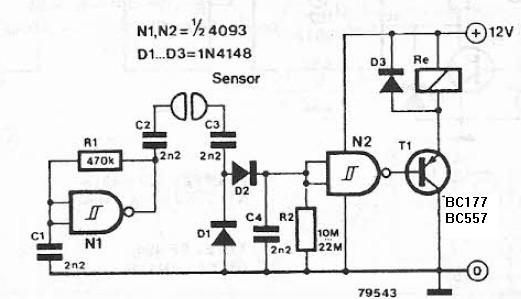
The liquid detector is a device designed to detect the presence of liquid using alternating voltage. This circuit can be constructed using common electronic components. The alternating voltage is generated by a gate with a Schmitt trigger function, acting...
This schematic diagram illustrates a 70W power amplifier utilizing MOSFET technology for audio systems. Alternative input stage transistors include the Toshiba 2SA970BL and 2SC2240BL, which serve as suitable substitutes for the Hitachi 2SA1085E. The 70W power amplifier is designed to...
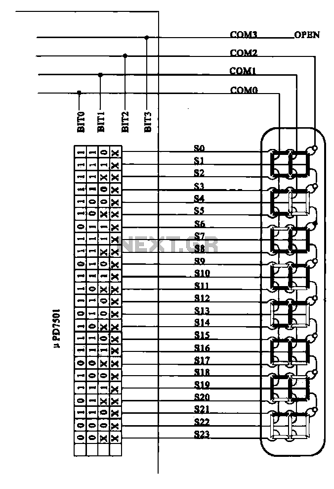
Examples of the structure of several liquid crystal display drive circuit CPU tubes. Liquid crystal display (LCD) drive circuits play a critical role in controlling the operation of LCD panels, which are widely used in various electronic devices. These circuits...
This article discusses the utilization of old PCs as simple controllers. Many obsolete systems, such as the 8088, 8086, 80286, 80386, and 80486, are no longer capable of running modern software, yet they can still function effectively. Often, individuals...