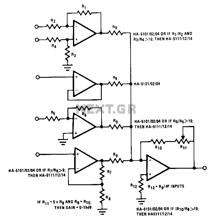
Universal-mixer-stage

This circuit illustrates various possible buffer combinations. These include a differential input stage, a voltage follower, as well as both non-inverting and inverting stages. The allowable resistor ratios and recommended device types are also included. One restriction applies to this type of mixer network in which Rg is greater than 2.4 kΩ. This limits the worst-case output current for each of the input buffers to less than 10 mA.
The circuit described features several buffer configurations that serve distinct purposes in signal processing. The differential input stage is essential for amplifying the difference between two input signals while rejecting common-mode noise, making it ideal for applications requiring high precision. The voltage follower configuration, also known as a unity gain amplifier, is utilized to provide impedance matching. It allows the output to follow the input voltage closely without loading the preceding stage, thus preserving signal integrity.
The inclusion of both non-inverting and inverting stages enhances the circuit's versatility. The non-inverting stage amplifies the input signal while maintaining its phase, which is crucial for applications where phase preservation is necessary. Conversely, the inverting stage provides a phase shift of 180 degrees and can be employed in applications where signal inversion is required.
The design specifies allowable resistor ratios that are critical for determining the gain and bandwidth of the buffers. The recommended device types should be selected based on their performance characteristics, such as bandwidth, input/output impedance, and power consumption, to ensure optimal circuit functionality.
An important design consideration is the limitation imposed on the resistor Rg, which must exceed 2.4 kΩ. This restriction is in place to safeguard the circuit by limiting the maximum output current to less than 10 mA for each input buffer. This current limitation is vital for preventing overheating and potential damage to the components, ensuring long-term reliability and stability of the circuit operation. The careful selection of resistor values and component specifications will ultimately dictate the performance and efficiency of the buffer configurations in various applications.This circuit illustrates some possible buffer combinations. Tbese include a differential input stage, a voltage follower as well as both noninverting and inverting stages. The allowable resistor ratios and recommended device types are also included. One restriction applies to this type of mixernetwork in which Rg is greater than 2.4 KO. This limits the worst case output current for each of the input buffers to less than 10 mA.