
Unsteady programmable circuit diagram
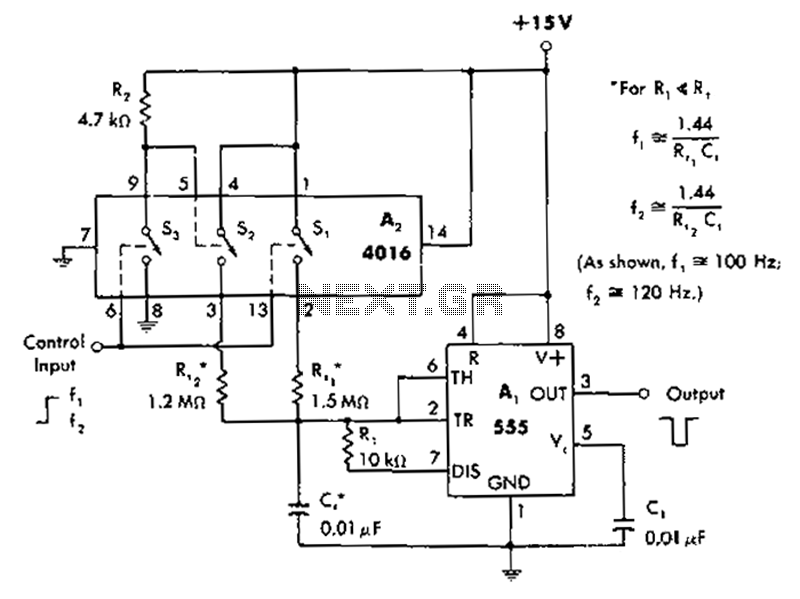
The described circuit utilizes a 4016 CMOS analog switch, which is a quad analog switch that allows for the selection of different resistive timing components based on the state of an input control signal. The circuit operates by routing the timing resistor through the analog switch to produce desired output frequencies.
When the input signal is high, the switch connects to a 1.5 megohm resistor (Rt1). This resistor, in conjunction with the associated capacitive components, determines the timing characteristics that yield a negative output pulse at a frequency of 100 Hz. The negative pulse indicates that the output signal transitions from a high state to a low state, producing a square wave with a specific frequency determined by the RC time constant.
In the alternate state, when the input signal is low, CMOS switch S2 opens, and the circuit selects a 1.2 megohm resistor (Rt2). This configuration alters the RC timing characteristics, resulting in an output frequency of 120 Hz. The choice of resistors directly affects the frequency of the output signal, illustrating the flexibility and utility of the analog switch in adapting the circuit's response based on input conditions.
The output pulses generated can be used for various applications such as timing circuits, frequency modulation, or as a clock signal for digital circuits. The precise control over the output frequency via resistor selection allows for fine-tuning in applications requiring specific timing intervals. The design ensures low power consumption typical of CMOS technology while providing reliable switching characteristics.A circuit diagram of the control when the input line is high time, 4016CMOS analog switches will choose the timing of 1.5 megohm resistor Rt1, to produce a negative 100Hz to ou tput pulses. When the input is low, CMOS switch S2 opens, select the 1.2 megohm resistor Rt2 timing to generate the output of 120Hz.
Related Circuits
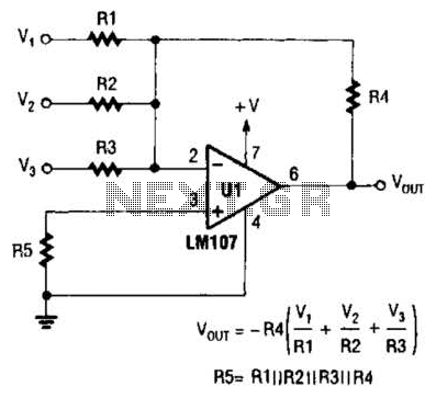
The output of Ul is the sum of Vv, multiplied by the ratio of Rx to Rv, RJRV, and respectively. Resistors R1, R2, and R3 are selected as required for individual gains. Additionally, R4 influences the gain of all...
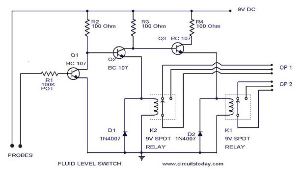
A simple liquid level switch circuit with diagram and schematic. This can also be used as a water level switch, fluid level switch, float level switch, and tank level switch. The liquid level switch circuit is designed to detect the...
This project involves a simple touch switch circuit that can also be utilized to activate a relay instead of an LED and resistor. The circuit exhibits high sensitivity due to the use of two transistors configured as a Darlington...
This is a simple proximity switch utilizing the IC 4049. The IC 4049 is a bipolar monolithic integrated circuit designed for metal detection systems and proximity sensing applications. It includes an oscillator formed by an external parallel resonant tank...

This circuit is designed to provide automatic current limiting up to 8.4 A. Unlike traditional current limiters that rely solely on a resistor, this circuit minimizes voltage drop until a specified current threshold is exceeded. The current limit can...
The all-analog circuit presented controls the rate at which a miniature turbojet engine can be throttled. Increasing or decreasing the throttle too quickly on a miniature turbojet engine, or any jet engine, can lead to quick failure in flight,...
Warning: include(partials/cookie-banner.php): Failed to open stream: Permission denied in /var/www/html/nextgr/view-circuit.php on line 713
Warning: include(): Failed opening 'partials/cookie-banner.php' for inclusion (include_path='.:/usr/share/php') in /var/www/html/nextgr/view-circuit.php on line 713