
Variable-duty-cycle-oscillator
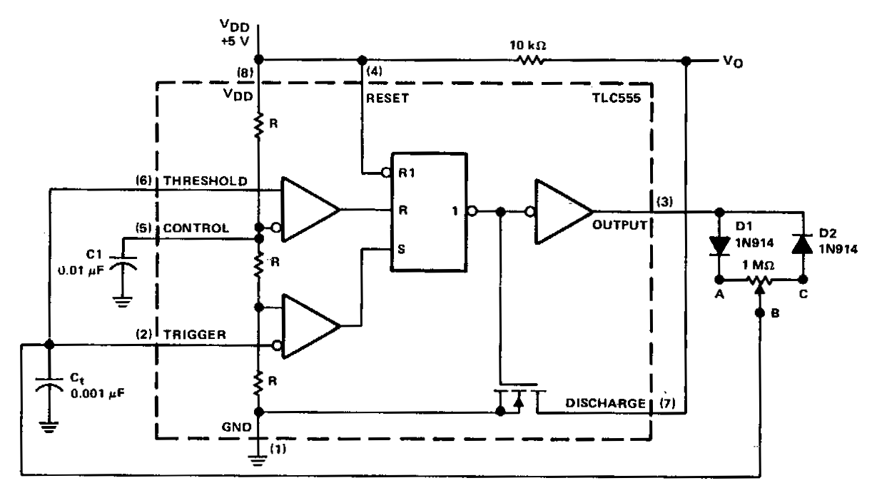
In a basic astable timer, the timing periods 11 and 12 are not independently controlled. This lack of control complicates the maintenance of a constant period, T, if either 11 or 12 is varied. In this circuit, the charge resistances RAB and discharge resistance R8c are determined by the position of the common wiper arm of the potentiometer. Therefore, it is possible to adjust the duty cycle by proportionately adjusting 11 and 12 without altering the period T. At startup, the voltage across capacitor C is less than.
The described astable timer circuit operates in a continuous oscillation mode, generating a square wave output. In this configuration, resistors RAB and R8c play crucial roles in determining the charge and discharge times of the timing capacitor, denoted as C. The timing periods, often referred to as T1 and T2, are influenced by the values of these resistors and the capacitor.
By utilizing a potentiometer with a common wiper arm, the resistances can be adjusted dynamically, allowing for fine-tuning of the duty cycle. The duty cycle is the ratio of the time the output is high (T1) to the total period of the waveform (T1 + T2). This feature is particularly advantageous in applications requiring specific timing characteristics without the need to redesign the circuit or replace components.
Upon startup, the capacitor C begins in a discharged state, resulting in a voltage across it that is initially lower than the triggering threshold required for the timer to switch states. As the capacitor charges through RAB, the voltage gradually increases until it reaches a level sufficient to trigger the timer's output. This process establishes the timing intervals, with the output switching states based on the timing periods defined by the resistor and capacitor values.
Overall, this astable timer configuration provides a versatile solution for generating adjustable timing signals while maintaining a constant frequency, making it suitable for various applications such as pulse-width modulation, frequency generation, and timing delays in electronic circuits.In a basic astable timer, configuration timing periods 11 and 12 are not controlled independently. The lack of control makes it difficult to maintain a constant period, T, if either 11 or 12 is varied. In this circuit, charge RAB and discharge R8 c resistances are detenriined by the position of common wiper arm~ of the potentiometer.
So, it is possible to adjust the duty-cycle by adjusting 11 and 12 proportionately, without changing period T. At start-up, the voltage across C, is less than. 🔗 External reference
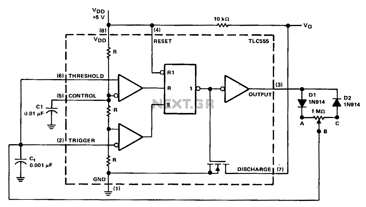
Related Circuits
In a basic astable timer configuration, timing periods 11 and 12 are not independently controlled. This lack of control complicates the maintenance of a constant period, T, when either 11 or 12 is varied. In this circuit, the charge...