
variable power supply with l200
The circuit described features a voltage output that is adjustable via a 10K variable resistor, allowing for a versatile range of output voltages from approximately 3 volts to 15 volts. The current specifications indicate a minimum output of 10mA and a maximum output of 2A. It is essential to note that reaching the maximum current limit will cause the output voltage to drop to zero, which serves as a protective measure to prevent damage to the circuit components.
For the PCB design process, the use of PCB design software such as Eagle is recommended. This software enables the user to create a schematic layout that can be printed. The printing process should utilize a laser printer for optimal results, as the toner will adhere better to glossy paper or photo paper. After printing, the design must be carefully aligned and affixed to the copper side of the PCB. The application of heat using a hot iron plate facilitates the transfer of the toner from the paper to the PCB surface, effectively creating a mask for the subsequent etching process.
Following the transfer of the design, the PCB is prepared for etching. This involves immersing the board in an etching solution that removes the unprotected copper, leaving behind the desired circuit traces. It is crucial to ensure that the design is printed accurately and that the transfer process is executed with precision to achieve a high-quality PCB. If access to a laser printer is limited, an alternative method involves printing the design on standard paper and utilizing a local copy service to transfer it onto glossy paper, ensuring that the final output remains usable for the PCB manufacturing process.Voltage output is controlled by 10K variable resistor. Output voltage range value will be about 3 to 15 volts, and current range is about 10mA minimum and 2 amp maximum. Reaching the current limit will reduce the output voltage to zero. Make a PCB in very easy steps. ! Create your PCB design using PCB designer software like Eagle, print out your design on photo paper or glossy paper with laserjet printer. Stick the printed design on the PCB (copper side) and then heat it using hot iron plate. The ink will stick on the PCB and it will be ready for etching process. Note: If you don`t have laserjet printer, then you can print the design on standard paper. Copy the printed design at Copy Service around your location (with glossy paper). 🔗 External reference
Related Circuits
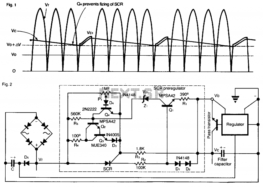
This SCR pre-regulator maintains the filter capacitor voltage (Vc) in a variable output power supply at a few volts above the output voltage (V0). The advantages include reduced heat dissipation by the pass transistor, resulting in a smaller heatsink,...
Simple and low cost. The optimal supply voltage is around 50V, but this amp works from 30 to 60V. The maximal input voltage is around 0.8 - 1V. As you can see, in this design the components have a...
Some amplifier is based around a RF transistor. In my case I will use a common NPN RF transistor called 2SC1970. You can also use other transistors like 2N4427 and some others. Check datasheets to see how much power...
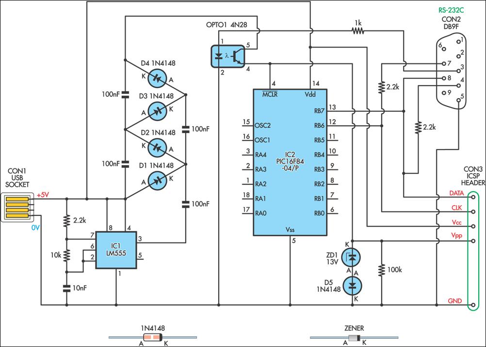
This simple circuit can be used to program the PIC16F84 and similar "flash memory" type parts. It utilizes a 555 timer IC to generate the programming voltage from a +5V rail, allowing the circuit to be powered from a...

Traditional soldering irons utilize mains AC supply for heating, which can be inconvenient in the absence of such a power source. This document describes a simple and cost-effective inverter circuit designed for use with standard soldering irons (25W, 30W,...
%2BCircuit%2Bdiagram%2Busing%2BCD4047%2Band%2BIRFZ44%2Bpower%2BMOSFET.png)
This simple low-power DC to AC inverter circuit converts 12V DC to either 230V or 110V AC. By making simple modifications, it is also possible to convert 6V DC to 230V AC or 110V AC. This inverter can be...
Warning: include(partials/cookie-banner.php): Failed to open stream: Permission denied in /var/www/html/nextgr/view-circuit.php on line 713
Warning: include(): Failed opening 'partials/cookie-banner.php' for inclusion (include_path='.:/usr/share/php') in /var/www/html/nextgr/view-circuit.php on line 713