
Variable Wein Bridge Oscillator Circuit

The circuit design incorporates a single potentiometer, which serves as a variable resistor, allowing for the adjustment of frequency within the specified range. The operational amplifiers (op-amps) used in this circuit are field-effect transistor (FET) types, known for their high input impedance and low noise characteristics, which are advantageous in frequency modulation applications.
At stage A1, the FET op-amp amplifies the input signal, with the gain set by the feedback network that includes the potentiometer. This stage is crucial for adjusting the amplitude of the output signal, ensuring that it remains within the optimal range for further processing.
Stage A2 continues the amplification process, further refining the signal. The gain-bandwidth product of the op-amps is a critical parameter, as it defines the maximum frequency at which the op-amps can effectively amplify the signal. In this circuit, the upper frequency limit of 3000 Hz is determined by this product, ensuring that the circuit can operate effectively across the entire frequency range.
Overall, the design emphasizes the importance of selecting appropriate components and configurations to achieve the desired frequency response. The use of a potentiometer for tuning provides flexibility, while the choice of FET op-amps ensures high performance and reliability in signal processing. This circuit uses a single potentiometer to time a 300- to 3000-Hz range. A FET op amp is used at A1 and A2. The upper frequency limit is determined by the gain-bandwidth product of the op amps. 🔗 External reference
Related Circuits
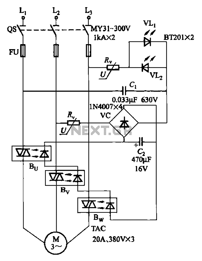
The circuit depicted in Figure 3-93 is integrated with an optical phase sequence protection relay. The circuit in question is designed to provide phase sequence protection using an optical relay mechanism. Optical phase sequence protection relays are crucial in applications...

The remote control circuit consists of two main components: the transmitter and the receiver. A simple schematic diagram illustrates the remote control setup. The transmitter circuit utilizes a NE555 timer IC to generate a specific frequency. The receiver circuit...
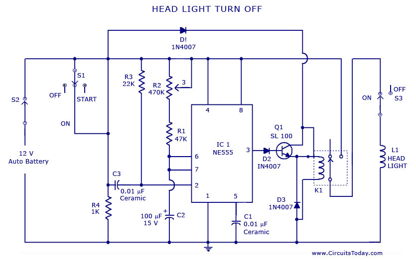
A circuit that can automatically turn off the headlights or lamps of a vehicle after a preset time. This light switching circuit is constructed using a 555 timer integrated circuit (IC). The described circuit utilizes the 555 timer IC in...
This circuit utilizes the MM74HC942, a single-chip low-speed modem that is compatible with the Bell 103 standard. The Bell 103 modem circuit operates at a baud rate of 300. The MM74HC942 is a versatile integrated circuit designed for low-speed data...
Solar panels operate at optimal parameters when positioned at the ideal angle to the sun. This alignment is achieved by rotating the solar panels to track the sun's movement. A DIY solar tracker system can be constructed using an...
A simple FM transmitter connects a home entertainment system to a portable radio that can be moved around the house and into the backyard. For instance, music can be played from a CD player in the living room and...