
Very-short-pulse-width-measurer
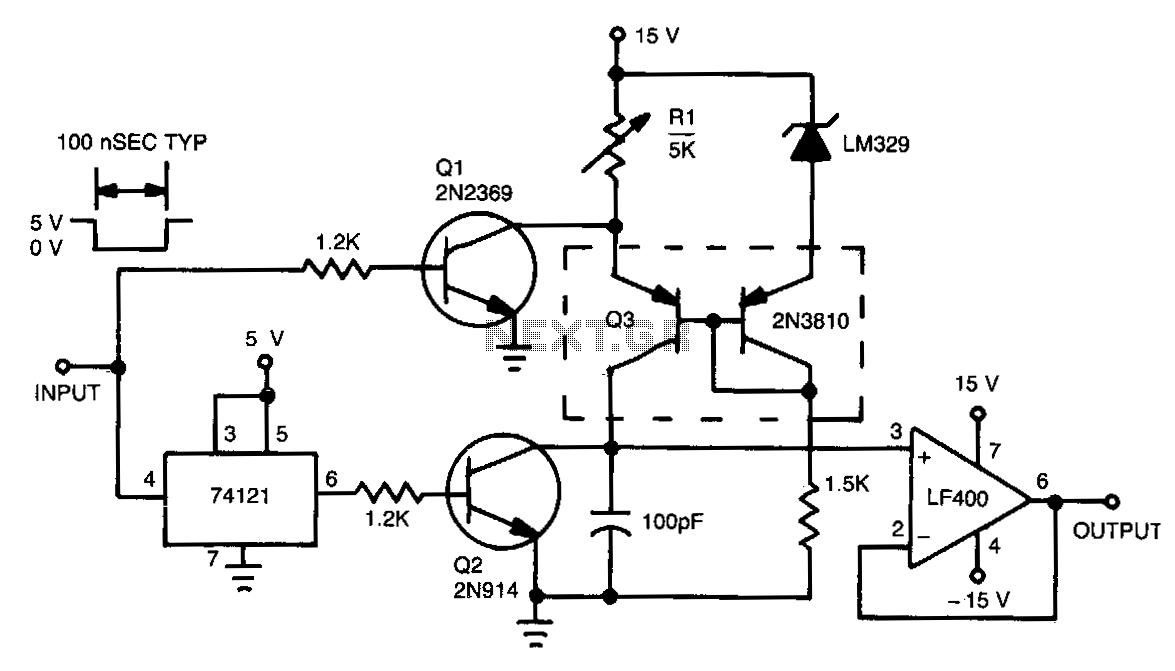
This circuit functions by charging a small capacitor using a constant-current source when a measurable pulse is present. The dual PNP transistor Q3 acts as the current source, with its output current determined by dividing the LM329 reference voltage by the resistance of potentiometer R1. When the input signal is high and no pulse is detected, transistor Q1 keeps the current source in an off state. Upon the onset of the pulse, the input signal decreases, causing Q1 to turn off, which triggers the monostable multivibrator to generate a brief pulse. The pulse output from the multivibrator activates transistor Q2, which discharges any residual charge from the 100-pF capacitor. After Q2 turns off, the capacitor begins to charge linearly from the current source. Once the input pulse concludes, the current source is deactivated, and the voltage across the capacitor becomes proportional to the width of the input pulse.
This circuit is designed to measure pulse widths accurately by utilizing a combination of transistors and a monostable multivibrator. The PNP transistor Q3 serves as a constant current source, ensuring that the capacitor charges at a steady rate, which is crucial for achieving precise measurements. The LM329 reference voltage provides a stable reference point, allowing for consistent performance despite variations in power supply or other environmental factors.
The operation begins with the detection of a pulse; when the input signal transitions from high to low, Q1 turns off, allowing the multivibrator to generate a short pulse. This pulse is essential for resetting the system, as it activates Q2 to discharge the capacitor and eliminate any previous charge that could lead to inaccurate readings. The 100-pF capacitor is selected for its small size and quick response time, which is vital for high-frequency pulse measurements.
As the capacitor charges, the linearity of the charging process ensures that the voltage across the capacitor directly correlates with the duration of the input pulse. This relationship enables the circuit to convert the width of the pulse into a measurable voltage, which can then be processed or displayed by additional circuitry. The design effectively isolates the measurement process from the input signal, allowing for accurate readings without interference from noise or signal fluctuations.
In summary, this circuit offers a robust solution for pulse width measurement, leveraging the properties of transistors and capacitors to achieve reliable and precise results. The careful selection of components and the configuration of the circuit ensure that it operates effectively across a range of conditions, making it suitable for various applications in electronics and signal processing.This circuit operates by charging a small capacitor from a constant-current source when the pulse to be measured is present. Dual pnp transistor Q3 is the current source; its output current equals the LM329 reference voltage divided by the resistance of potentiometer Rl.
When the input is high with no pulse present, Ql keeps the current source turned off. When the pulse begins and the input decreases, Ql turns off and the monostable multivibrator generates a short pulse. The pulse from the multivibrator turns on Q2, removing any residual charge from the 100-pF capacitor. Q2 then turns off, and the capacitor begins to charge linearly from the current source. When the input pulse ends, the current source turns off, and the voltage on the capacitor is proportional to the pulse width.
🔗 External reference