
vhf ampand transmiter schematic
The 1W VHF amplifier circuit is designed to enhance the signal strength for FM transceiver applications. The core of the amplifier utilizes bipolar junction transistors (BJTs) such as the 2N2553 and 2N2866, which are selected for their performance characteristics in VHF range applications. The circuit is configured to maximize power output while maintaining stability and minimizing distortion.
The inclusion of a 27 Ohm resistor in the base circuit is crucial for biasing the transistor correctly, ensuring it operates within its optimal range. The unusual failure of this resistor, resulting in solder melting, indicates a potential issue with excessive current or thermal management within the circuit. This necessitates careful consideration of component ratings and thermal dissipation strategies to prevent future failures.
The schematic provided by Pedro - CT5JZX serves as a valuable reference, reinforcing the importance of peer collaboration in circuit design. The similarities with existing designs highlight common practices in VHF amplifier construction, where the choice of components and configuration often leads to similar outcomes in performance.
The use of a BFR91 transistor as a VHF oscillator buffer is a strategic choice, as it is well-suited for high-frequency applications. The 100k resistor at the base of the BFR91 helps to set the operating point, ensuring that the transistor functions effectively within the desired frequency range. The dual buffer configuration allows for separation of the PLL and output amplifier stages, which is essential for maintaining signal integrity and minimizing interference between the two sections. The DC decoupling capacitors play a critical role in blocking DC while allowing AC signals to pass, thus ensuring that each stage operates independently without undesired interactions.
In summary, this VHF amplifier design incorporates essential elements for successful operation, including careful component selection, biasing strategies, and circuit topology that facilitates effective amplification while addressing potential failure points. Further experimentation and refinement will enhance understanding and performance in VHF amplification endeavors.Another version of the 1W VHF amplifier for the FM transceiver, well, in fact, it`s still the same version since I didn`t managed to get 1W. YET! Today I made some tests with a 2n2553 and a 2n2866. it melted solder in one of the base resistors (never I had seen such a thing, normaly resistors burn), a 27 Ohm one, made with 3 different resistor.
but the power was: 1. 6mW thats mili! So I still have to learn a little more on VHF amplification. 2 more 2n3553 went belly up. it`s always the emiter junction that breaks :) Anyhow, Pedro - CT5JZX, today sent me a schematic he found for me to have a look and get some ideas! Funny, it`s basically the same schematic I use on the transmitting part, that`s normal, most parts of my schematic came from Miguel - PY2OHH site.
VHF oscilator buffer (BFR91 with 100k to base): I have two, one for the PLL and the other for the output amp part. Both connect to the same place via DC decoupling caps. 🔗 External reference
Related Circuits
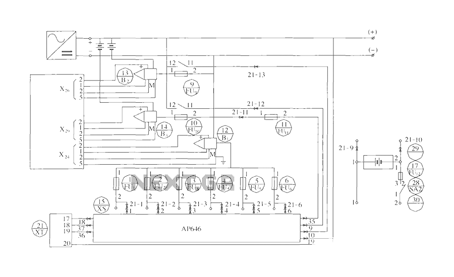
The components include B2 (13) and B3 (14) designated for the Hall current sensor; FU9 (9) and FU10 (10) serve as fuses; an AP646 alarm signal is connected to the fuse board; terminals X24, X26, and X29 function as...
To construct the circuit, follow the provided schematic. If assistance is required, do not hesitate to reach out for support. If there are difficulties in identifying the components... To build the circuit effectively, it is essential to adhere closely to...
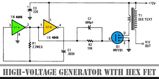
The schematic diagram below illustrates a high voltage generator circuit. This circuit employs a 4049 hex inverter configured as an oscillator, and it can utilize an ignition transformer from an automotive engine. A fly-back transformer may also be suitable....
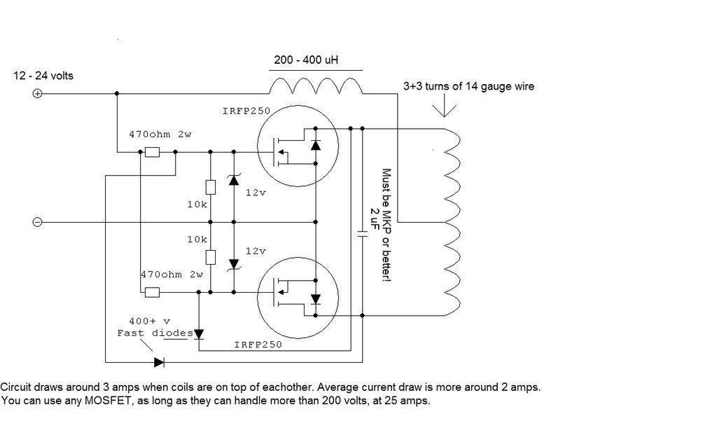
Unlike many units, this battery charger continuously charges at maximum current, tapering off only near full battery voltage. In this unit, the full load. This battery charger is designed to operate with a continuous charging mechanism, maintaining the maximum current...
Everybody likes re-discovering something they did years ago. Here's a game we all played at school. Possibly under the name of HANG THE BUTCHER. The game is quite simple. One player thinks of a word and writes down the...
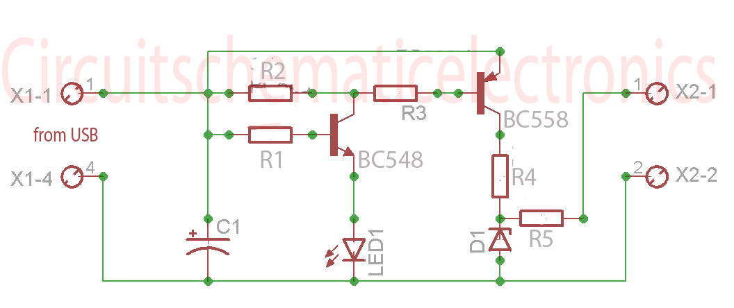
Without a USB to phone battery charger circuit, charging a phone battery using a USB port on a computer can quickly damage the battery, resulting in bulging. This occurs because the voltage output from USB is 5 volts, while...