
Vhf-modulator
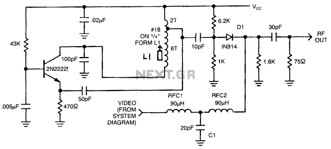
This circuit utilizes an oscillator (2N2222) and a diode (D1) as a nonlinear mixer. The frequency is determined by a slug in inductor (L1). Additionally, RFCl, C1, and RFC2 create a low-pass filter that allows video signals to pass while blocking radio frequency signals from the video source.
The described circuit incorporates a 2N2222 transistor functioning as an oscillator, which generates a high-frequency signal suitable for mixing. The oscillator's frequency can be adjusted by manipulating a slug within inductor L1, allowing for fine-tuning of the output frequency to match the desired operational parameters.
The nonlinear mixer employs diode D1 to combine the oscillator output with an incoming RF signal. This mixing process produces new frequencies, which are the sum and difference of the original frequencies, enabling the extraction of the desired video signal from the RF carrier.
The low-pass filter configuration, consisting of RFCl, C1, and RFC2, is critical in this application. RFCl serves as a radio frequency choke, effectively blocking high-frequency signals while allowing lower-frequency video signals to pass through. Capacitor C1 further aids in this filtering process by providing a path to ground for unwanted RF signals. RFC2 complements this arrangement by ensuring that only the desired frequency components reach the output, thereby enhancing the quality of the video signal while suppressing any extraneous RF interference.
Overall, this circuit is designed to efficiently mix and filter signals, making it suitable for applications in video processing and RF communication systems where signal integrity is paramount.This circuit uses an oscillator (2N2222) and a diode Dl as a nonlinear mixer. The frequency is set by a slug in Ll. RFCl, Cl, and RFC2 form a low-pass filter to pass video and block rffrom the video source. 🔗 External reference
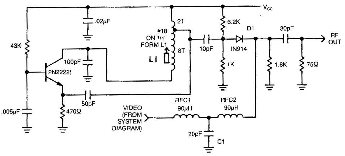
Related Circuits
This circuit utilizes an oscillator (2N2222) and a diode (D1) as a nonlinear mixer. The frequency is determined by a slug in L1. RFCl, C1, and RFC2 create a low-pass filter designed to pass video signals while blocking RF...