
VHF radio receiver
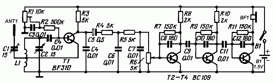
The FM receiver schematic operates by first capturing radio frequency signals through the antenna, which is coupled to the resonant tank circuit formed by L1 and C2. The trimmer capacitor C1 plays a crucial role in optimizing the antenna's coupling efficiency, allowing for better signal reception. The super-regenerative detector, implemented with transistor T1, demodulates the incoming FM signals, converting them into audio frequencies. The regeneration adjustment via potentiometer R1 is essential for maximizing sensitivity and selectivity, ensuring that the receiver can effectively distinguish between different frequencies.
Following demodulation, the audio signal is filtered through a low-pass filter designed to eliminate high-frequency noise that could interfere with audio clarity. This filtering stage is critical as it enhances the overall sound quality delivered to the audio amplifier stages. The audio amplifier, composed of transistors T2, T3, and T4, amplifies the filtered audio signal. The incorporation of negative AC feedback through capacitors C8, C10, and C12 stabilizes the amplifier's gain and reduces distortion, resulting in a cleaner audio output.
The design of coil L1 is significant, as its dimensions and the number of turns directly influence the tuning characteristics of the receiver. The choice of silver-plated wire for the coil enhances conductivity, thereby improving performance. The ability to tap the coil at its midpoint allows for flexibility in tuning, enabling the receiver to operate effectively across the specified frequency range of 100 to 170 MHz. This configuration makes the FM receiver suitable for various applications, including personal listening and educational demonstrations in radio frequency technology.The figure below shows a schematic diagram of a simple FM receiver. This receiver made with four transistors. The signal from the antenna through the trimmer capacitor C1 goes to the input of the first stage. This stage is a super-regenerative detector based on the transistor T1 circuit. The potentiometer R1 is used to adjust the regeneration. The trimmer C1 is used to adjust the coupling of the antenna to the resonant tank L1C2. An audio signal from the output of the super-regenerative detector through a low-pass filter is fed to an audio amplifier. The filter reduces the noise level at the input of the audio amplifier. The audio amplifier is based on transistors T2-T4. Each stage of the amplifier has a negative AC feedback loop (capacitors C8, C10 and C12). A load of the amplifier is the high-impedance headphones. The coil L1 is wound on a mandrel of diameter 12 mm and length of 10 mm. It contains 3 turns of silver-plated wire with a diameter of 1. 5 mm (AWG 15). The coil L1 is tapped in the middle. With this coil the frequency range is 100. 170MHz. 🔗 External reference
Related Circuits
For the regulation needs a transmitter or generator in mpa'nta the CB, that is to say in the region 27MHz. If you have a certain friend with CB, you convince you to help. Connect a piece of cable around...
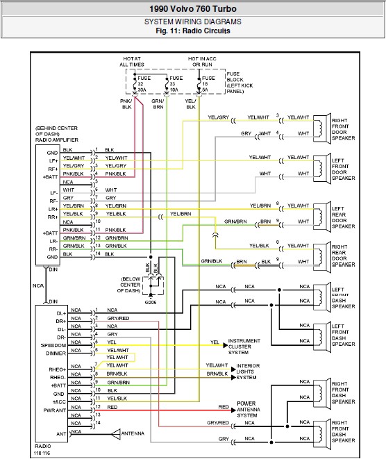
The following document contains the system wiring diagram of the radio circuit for the Volvo 760 Turbo 1990. Please note that this is a system wiring diagram, not a schematic diagram. Download the radio circuit system wiring for the...
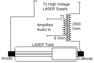
This set of two circuits forms the basis for a simple light wave transmitter. A laser beam is modulated and directed toward a receiver that demodulates the signal, subsequently presenting the information (voice, data, etc.). The assembly is straightforward and...
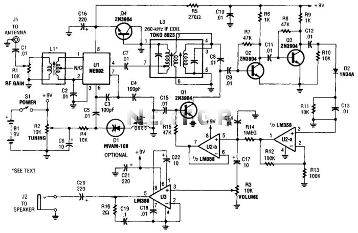
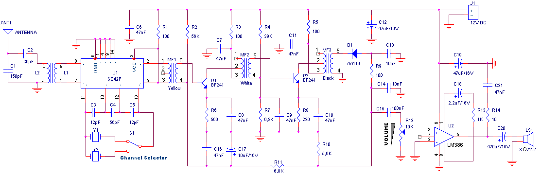
The integrated circuit Ul (an NE602 double-balanced mixer) functions as both an oscillator and a frequency mixer. Signals from the antenna input (at Jl) are transmitted through a DC-blocking capacitor C1 to the RF gain control, Rl, and subsequently...
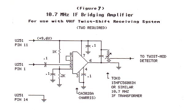
The material in this section demonstrates the construction of the Twist-Shift system for VHF utilizing commonly available surplus land mobile VHF transceivers that have been modified to operate on the 2-meter ham band. The radios employed in this project...
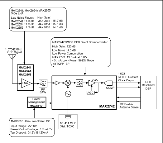
The following circuit illustrates the RF block diagram of a GPS receiver. This circuit is based on the MAX2742 integrated circuit. Features include a complete GPS receiver functionality. The GPS receiver RF block diagram utilizing the MAX2742 IC encompasses several...