
VHF Stability
The VHF systems operate within a unique set of parameters that dictate the design and implementation of circuits. Understanding the behavior of VHF energy is crucial for effective circuit design, particularly in applications such as RF amplifiers and transmitters. The wavelength at VHF frequencies is short, leading to the necessity of considering the physical dimensions of components and pathways in relation to the wavelength. The relationship between frequency, wavelength, and impedance becomes essential, as incorrect assumptions regarding component placement can lead to significant performance issues.
In practical applications, the layout of circuits should prioritize short and wide conductive paths to minimize inductive and capacitive effects that can distort signal integrity. The use of wide conductors or ground planes is recommended to ensure low impedance connections, which is particularly important in VHF applications where even small deviations can lead to performance degradation. The design of tuning networks and suppressors must be approached with a comprehensive understanding of their role within the entire circuit, rather than as isolated components. This holistic view is necessary to optimize the performance of VHF systems, as each component interacts with others in ways that can significantly influence overall behavior.
In conclusion, the design of VHF systems requires careful consideration of the physical properties of conductors, the implications of electrical lengths, and the interactions between components. A thorough understanding of these principles is essential for achieving optimal performance in VHF applications.The intelligent discussion of VHF systems requires a feel for VHF systems, and how VHF energy moves through a system. At VHF, wavelength is very short. Wavelength in feet is F/983. 6, a typical 150 MHz system would have a quarter wavelength of 19. 8 inches. This does not include velocity factor of dielectric, or unevenly distributed series inductances or shunt capacitances, which can make electrical distance along a conductor appear much longer than it is. The general rule of thumb is two electrical degree length paths will have a negligible effect on system impedances.
While that is 3 feet on 160 meters, two electrical degrees is roughly 1/2 inch on 150 MHz. A 10-inch long conductor, in particular a thin conductor with a dielectric, is just like having no path at all for VHF, yet we see Internet suggestions of adding thin wires from grid pins up to tuning capacitors to beneficially alter the path from tuning capacitor to grid in some amplifier layouts! This is the same false notion Johnson engineers used in the Valiant and Ranger transmitters. In the image below, Johnson used a buss wire to ground tuning capacitors to the 6146 socket ground, which turns out to be a disaster for ground loops and VHF harmonic suppression.
A similar fallacy exists in HF amplifiers, where people add an even thinner and longer wire from tuning capacitors to the grid pins of tube sockets. A Kenwood TL922 I worked on had just such a mod, clearly the installer had no idea about wavelengths and transmission line behavior.
They used a thin wire several inches long, shown below, in an attempt to reduce tuning capacitor to grid path impedance! VHF paths must be short and very wide, and ideally would be smooth surfaces. A wide path acts more like a groundplane, instead of a transmission line. For example, a 20-inch metal radius makes a very low impedance ground path at VHF, yet a 20-inch thin wire can look like no ground connection at all between two points!
If we want reasonable results, we have to stop following unreasonable logic or junk science when making changes. If a tuning capacitor is poorly connected back to the grid at VHF, because the path through 10-inch wide sheet is too long, we are NOT going to improve it with an additional several inches length of.
060 inch wide conductor in parallel. The notion something so thin in parallel with a wide ground plane helps reduce path impedance is silly. A similar error occurs in a west coast amateur`s discussions of VHF suppressors. He treats the VHF suppressor as an isolated component that solely determines anode system Q. The anode suppressor is actually one small section of a much longer path that behaves like a transmission line.
The suppressor Q, in isolation, means very little to overall system behavior. We have to look at the suppressor in full context of how it modifies a much more complex system`s overall impedance. This is why every suppressor, when optimized, must be optimized for a particular system. As we see when we look at commercial designs, one size does not fit all. In many cases no suppressor at all is required, and when required, depending 🔗 External reference
Related Circuits
Once again my collection of projects creation has been interrupted by another necessity. Patrick and other people have asked me for a circuit of a VHF power amplifier. These circuits are my "standard" building blocks that can be used...
A use has been found for a collection of DIP-style RF relays acquired from a discount electronics shop. These relays are completely sealed and RF shielded, featuring low contact capacitance, making them suitable for VHF frequencies. They operate at...
An Icom PCR-1000 is utilized for listening to various MF, HF, and VHF radio stations. There is a minor inconvenience related to the antennas. The K9AY antenna performs well from 500 KHz to approximately 25 MHz, while the discone...
This compact transmitter employs a Hartley oscillator configuration. Typically, the capacitor in the tank circuit connects to the base of the transistor; however, at VHF frequencies, the base-emitter capacitance of the transistor behaves like a short circuit, maintaining its...
The 30-watt amplifier schematic provided below offers a power boost from an input of 4 watts to 6 watts. This circuit is designed to operate within the 88-108 MHz FM broadcast band. It demonstrates stability and delivers a clean...
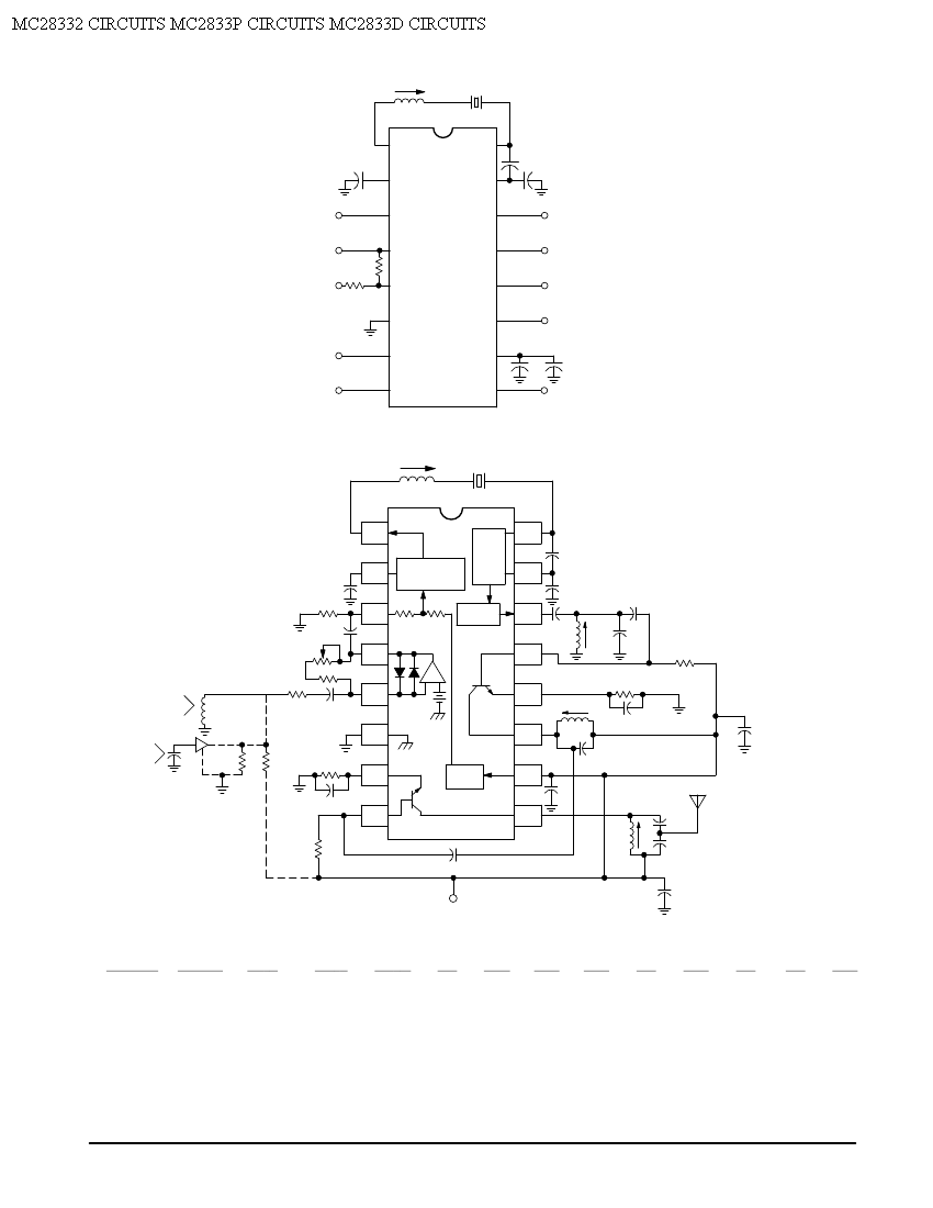
Crystal X1 operates in fundamental mode and is calibrated for parallel resonance with a load capacitance of 32 pF. The final output frequency is produced through frequency multiplication within the MC2833 integrated circuit (IC). The RF output buffer at...
Warning: include(partials/cookie-banner.php): Failed to open stream: Permission denied in /var/www/html/nextgr/view-circuit.php on line 713
Warning: include(): Failed opening 'partials/cookie-banner.php' for inclusion (include_path='.:/usr/share/php') in /var/www/html/nextgr/view-circuit.php on line 713