
Video Activated Relay
The circuit described is designed to detect a composite video signal and activate a relay in response. This functionality enables the control of devices such as older televisions that do not have remote control capabilities, as well as other electronic equipment like surround sound systems and game consoles.
The components of the circuit include several resistors (R1, R2, R3, and R4), capacitors (C1), transistors (Q1, Q2, and Q3), diodes (D1, D2, and D3), a relay (K1), and an RCA jack (J1). The resistors are primarily used to limit current and set biasing levels for the transistors, which play a crucial role in amplifying the detected video signal. The 10K resistors (R1 and R2) are likely used for input impedance and signal conditioning, while the 1K resistor (R3) and the 33K resistor (R4) help in defining the operating points of the transistors.
The 1uF electrolytic capacitor (C1) is used for coupling or decoupling purposes, ensuring that only the AC component of the video signal is passed to the transistors. The transistors (Q1, Q2, Q3) are NPN types, specifically the 2N2222 and 2N3904, which are suitable for switching applications and can handle the relay’s control current. The diodes (D1, D2, D3) are used for flyback protection across the relay coil to prevent back EMF from damaging the transistors when the relay is de-energized.
The relay (K1) is rated for 9V, allowing it to switch on or off the connected devices based on the presence of a composite video signal. The RCA jack (J1) serves as the input connection for the video signal.
To ensure safety, particularly when dealing with mains voltage, the entire circuit should be housed in a suitable enclosure. This prevents accidental contact with live components and minimizes the risk of electrical shock. Additionally, the circuit's versatility allows it to be adapted for various applications, including switching audio signals, although adjustments to resistor values may be necessary to optimize performance for different signal levels.This simple circuit from the May 1996 Think Tank column of Popular Electronics activates a relay when it senses a composite video signal. This allows you to use the tuner built into your VCR to turn on and off older TVs that are not equipped with a remote.
It can also be used to activate surround sound equipment, turn off the room lights, turn on video game consoles, etc. For such a simple circuit, it is very versatile. R1, R2 2 10K 1/4 W Resistor R3 1 1K 1/4 W Resistor R4 1 33K 1/4 W Resistor C1 1 1uF Electrolytic Capacitor Q1, Q2, Q3 3 2N2222 NPN Transistor 2N3904 NPN Transistor D1, D2, D3 4 1N4148 Diode K1 1 9V Relay J1 1 RCA Jack MISC 1 Case, wire, board Since you may be using this circuit to switch mains voltage, it should be enclosed in a case. The circuit will also work with most line level audio, although you may have to adjust the value of R1.
🔗 External reference
Related Circuits

This relay driver enhances the input impedance using a standard BC547 NPN transistor (or its equivalent). It is a widely used driver capable of operating various relays, including reed relays. Transistors Q1 and Q2 function as a simple common-emitter...
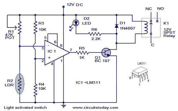
A simple light-activated switch circuit with a diagram and schematic using IC LM311 wired as a voltage comparator and an LDR that acts as a light sensor. The described circuit utilizes the LM311 integrated circuit, which functions as a voltage...
A time delay relay is a relay that remains activated for a specific duration after being triggered. This type of relay consists of a straightforward adjustable timer circuit that regulates the operation of the relay. The timing can be...

This circuit is similar to the one above, but uses a N channel mosfet such as IRF530, 540, 640, etc. in place of the NPN transistor. Smaller mosfets could be used, but I don't know the part numbers. I...
A simple thermostat circuit that can control a relay to supply power to a small space heater through the relay contacts. The relay contacts must be rated above the current requirements for the heater. Temperature changes are detected by...
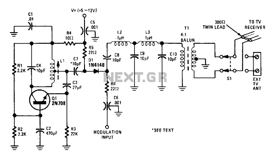
This circuit allows for the direct connection of composite video signals from video game consoles and microcomputers to the antenna terminals of television sets. The output signal level is regulated by the modulation input. The circuit is designed to facilitate the...
Warning: include(partials/cookie-banner.php): Failed to open stream: Permission denied in /var/www/html/nextgr/view-circuit.php on line 713
Warning: include(): Failed opening 'partials/cookie-banner.php' for inclusion (include_path='.:/usr/share/php') in /var/www/html/nextgr/view-circuit.php on line 713