
Video-gain-block
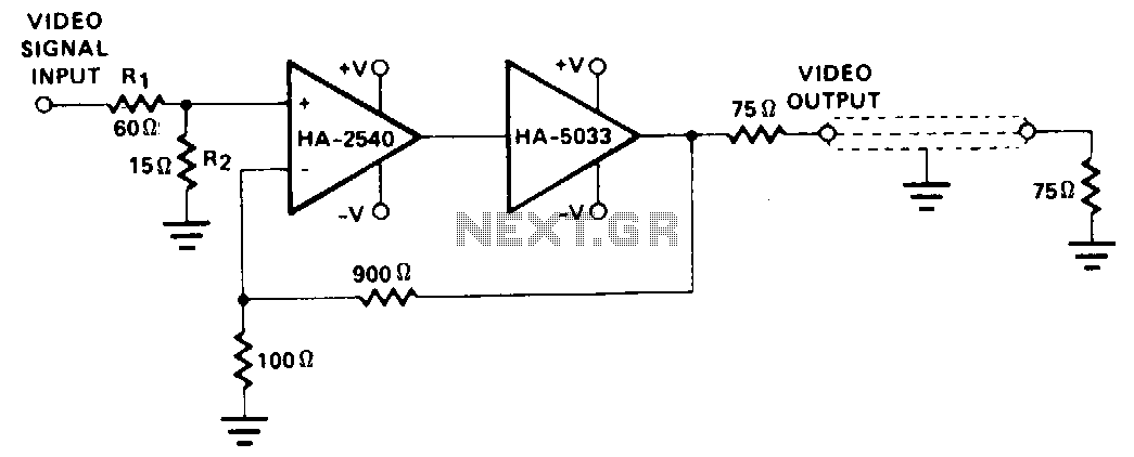
This configuration employs the wide bandwidth and high speed of the HA-2540, in conjunction with the output capabilities of the HA-5033. Stabilization circuitry is not implemented, as the HA-2540 operates at a closed-loop gain of 10 while maintaining an overall block gain of unity. A maximum block gain of 3 is advised to avoid signal distortion. Testing of this circuit for differential phase and differential gain was conducted using a Tektronix 520A vector scope and a Tektronix 146 video signal generator; however, both differential phase and differential gain were found to be too minimal to measure.
This circuit design integrates the HA-2540 operational amplifier, known for its high bandwidth and speed, with the HA-5033, which provides robust output capabilities. The choice to operate the HA-2540 at a closed-loop gain of 10 is significant, as it allows for high performance without the need for additional stabilization circuitry. This design decision simplifies the circuit and reduces potential sources of noise and instability, which are critical in high-frequency applications.
Maintaining an overall block gain of unity is essential for preserving signal integrity throughout the circuit. The recommendation for a maximum block gain of 3 serves as a precautionary measure to mitigate signal distortion, ensuring that the output remains faithful to the input signal. This is particularly important in applications where precision is paramount, such as in communication systems or high-fidelity audio equipment.
The testing methodology employed for this circuit utilized a Tektronix 520A vector scope in conjunction with a Tektronix 146 video signal generator. These instruments are well-suited for analyzing differential signals, allowing for precise measurements of phase and gain characteristics. However, the results indicated that both differential phase and differential gain were too small to be accurately measured, suggesting that the circuit operates within a range that is either highly linear or that the parameters being measured are below the threshold of the testing equipment's sensitivity.
In summary, this circuit configuration showcases a careful balance between high-speed operation and signal integrity, making it suitable for applications requiring minimal distortion and high fidelity. The design choices made regarding gain and the avoidance of stabilization circuitry reflect a commitment to achieving optimal performance in demanding electronic environments.This configuration utilizes the wide bandwidth aod speed of HA-2540. plus the output capability of HA5033. Stabilization circuitry is avoided by operating HA-2540 at a closed loop gain of 10, while maintaining an overall block gain of unity. A maximum block gain of 3 is recommended to prevent signal distortion. This circuit was tested for differential phase aod differential gain using a Tektronix 520A vector scope and a Tektronix 146 video signal generator. Both differential phase and differential gain were too small to be measured. 🔗 External reference