
video on telephone line wires
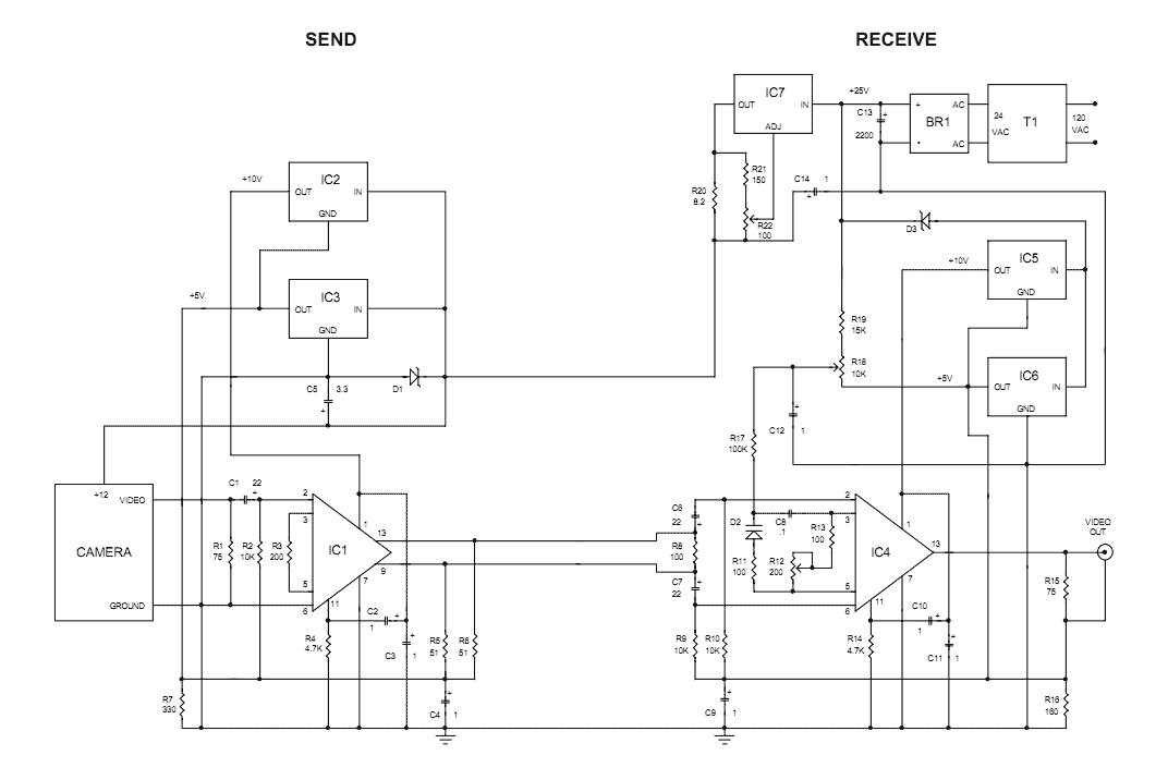
Two 78L05 voltage regulators IC5, IC6 and pulldown resistor R16 function the same as IC2, IC3 and R7 described above to supply power for amplifier IC4. The purpose of 10 volt Zener diode D3 is to reduce the voltage applied to IC5 and IC6 to avoid exceeding their input voltage rating and to reduce their power dissipation. The differential video signal from the send board feeds through C6 and C7 into the inputs of IC4, a MAX436 single output wideband transconductance amplifier. R8 terminates the lines and R9, R10 keep the IC4 inputs at a common mode voltage of +5 volts. Potentiometer R12 varies the gain of the amplifier to compensate for line losses. D2 is a variable capacitance diode to provide high frequency compensation. Potentiometer R18 varies the capacitance of D2 by changing its reverse bias. Amplifier operating current is set by R14. The output is terminated in 75 ohms by R15.
The Videowire’s current mode power system is the key to its ability to drive operating voltages for the camera and send board over very long, highly resistive wire. Power for the camera and both Videowire boards is supplied by 24 volt AC adapter transformer T1, DIP bridge rectifier BR1 and 2200 mfd filter capacitor C13. Power for the send board and camera goes through LM317 voltage regulator IC7 connected as a constant current source. Its output current can be varied from about 160 ma to 260 ma for use with different types of cameras by adjusting potentiometer R22. The power supply is designed to provide about 26 volts which is more than twice the 12 volts required by the boards and camera. There is a small voltage loss in R20 but most of the additional voltage is used to compensate for the voltage drop in long lines between boards. This means that a voltage drop of 10 to 14 volts, depending on the camera current, can be tolerated in the telephone wire while still maintaining 12 volts at the camera and send board. The LM317, operating as a current regulator, automatically raises its output voltage to compensate for increased wire resistance so that no adjustments are needed when wire length is changed.
The Videowire is designed for use with cameras that draw between 80 and 180 ma. The operating current of the send board is 60 ma. If, for example, a camera that draws 100 ma is used then a total of 160 ma must be supplied, and about 10 to 20 ma extra current to guarantee that 12 volts will always be present at the send board. The surplus current above 160 ma is then shunted by Zener diode D1.
Videowire Parts List
Description Source
R1, R15 - 75 ohms 1/8 watt Digi Key
R2, R9, R10 - 10K 1/8 watt Digi-Key
R3 - 200 ohms 1/8 watt Digi-Key
R4, R14 - 4.7K 1/8 watt Digi-Key
R5, R6 - 51 ohms 1/8 watt Digi-Key
R7 - 330 ohms 1/8 watt Digi-Key
R8, R11, R13 - 100 ohms 1/8 watt Digi-Key
R12 - 200 ohms potentiometer Digi-Key
R16 - 160 ohms 1/4 watt Digi-Key
R17 - 100K 1/8 watt Digi-Key
R18 - 10K potentiometer Digi-Key
R19 - 15K 1/8 watt Digi-Key
R20 - 8.2 ohm 1/2 watt Digi-Key
R21 - 150 ohm 1/8 watt Digi-Key
R22 - 100 ohm potentiometer Digi-Key
R dummy - 100 ohm 2 watt Digi-Key
C1 - 22 mfd 6.3 volt tantalum Digi-Key
C2, C3, C4, C9, C10, C11, C12 - 1 mfd 16 volt tantalum Digi-Key
C5 - 3.3 mfd 16 volt tantalum Digi-Key
C6, C7 - 22 mfd 16 volt tantalum Digi-Key
C8 - .1 mfd 50 volt metalized film Digi-Key
C13 - 2200 mfd 50 volt electrolytic Digi-Key
C14 - 1 mfd 50 volt tantalum Digi-Key
D1 - 12 volt 1 watt zener diode
D2 - Motorola MVAM109 tuning diode DC Electronics
D3 - 10 volt 1 watt zener diode
BR1 - 1 amp 400 volt DIP bridge rectifier
IC1 - Maxim MAX435 dual output amplifier Digi-Key
IC2, IC3, IC5, IC6 - 78L05 voltage regulator
IC4 - Maxim MAX436 single output amplifier Digi-Key
IC7 - LM317 adjustable voltage regulator
J1 - RJ11 6P4C telephone jack with leads Mouser
J2 - RJ11 6P4C board mount telephone jack Mouser
J3 - chassis mount angle coaxial F connector Mouser
four conductor telephone wire with RJ11 plugs
TO220 5 watt clip on heat sink Digi-Key
four threaded spacers 6-32 X 1/2 inch long
eight 6-32 X 1/4 inch screws
rubber grommet for 1/4 inch hole
2.2 X 3.3 X 4 inch metal enclosure with vent holes Jameco
T1 - 24 volt AC 400 ma adapter transformer JamecoThe Videowire converts a baseband video signal into a low impedance differential signal that can be sent over ordinary four conductor telephone wire. A send board mounted close to the camera generates the differential signal and a receive board near the monitor converts it back into single wire video that is fed to a monitor.
The video signal is sent over two of the four conductors in the telephone wire and power for both the send board and the camera are carried over the other two conductors. The telephone wire connects to the boards with standard RJ11 modular plugs. The send board can be attached to the back of a camera board with pieces of double sided tape or insulated with some electrical tape and tucked anywhere in the camera enclosure.
The receive board can be housed in a small metal enclosure. Figure 1 is a block diagram showing power and signal flow. The send board uses a MAX435 dual output wideband transconductance amplifier to convert the NTSC video from the camera into a differential signal. Each output line is terminated in 50 ohms and connects to the red and green center wires of the flat telephone wire.
Twelve volt DC power for the amplifier and camera is supplied by the receive board and is carried over the outer yellow and black wires. The MAX435 is designed to operate on - 5 volts, ground and + 5 volts. However, in this application it operates on ground, +5 volts and +10 volts. Circuit components that would normally connect to ground are connected to +5 volts instead. Two 78L05 voltage regulator ICs generate the +5 and +10 volts to power the MAX435, while a 12 volt Zener diode regulates power to the camera.
The 12volt DC power that is regulated by D1 and powers the camera also connects to the inputs of IC2 and IC3. IC3 provides a +5 volt output. The ground terminal of IC2 connects to +5 volts instead of ground, causing its output to be +10 volts.
Pulldown resistor R7 sinks the quiescent current of IC2 and the output drive current of IC1 to keep positive current flowing out of IC3 at all times. The video signal from the camera is terminated by R1 and coupled to the amplifier input through C1.
R2 provides a +5 reference for the input, R3 sets the amplifier gain at 1 and R4 sets its operating current. Two 78L05 voltage regulators IC5, IC6 and pulldown resistor R16 function the same as IC2, IC3 and R7 described above to supply power for amplifier IC4.
The purpose of 10 volt Zener diode D3 is to reduce the voltage applied to IC5 and IC6 to avoid exceeding their input voltage rating and to reduce their power dissipation. The differential video signal from the send board feeds through C6 and C7 into the inputs of IC4, a MAX436 single output wideband transconductance amplifier.
R8 terminates the lines and R9, R10 keep the IC4 inputs at a common mode voltage of +5 volts. Potentiometer R12 varies the gain of the amplifier to compensate for line losses. D2 is a variable capacitance diode to provide high frequency compensation. Potentiometer R18 varies the capacitance of D2 by changing its reverse bias. Amplifier operating current is set by R14. The output is terminated in 75 ohms by R15. The Videowire’s current mode power system is the key to its ability to drive operating voltages for the camera and send board over very long, highly resistive wire. Power for the camera and both Videowire boards is supplied by 24 volt AC adapter transformer T1, DIP bridge rectifier BR1 and 2200 mfd filter capacitor C13.
Power for the send board and camera goes through LM317 voltage regulator IC7 connected as a constant current source. Its output current can be varied from about 160 ma to 260 ma for use with different types of cameras by adjusting potentiometer R22.
The power supply is designed to provide about 26 volts which is more than twice the 12 volts required by the boards and camera. There is a small voltage loss in R20 but most of the additional voltage is used to compensate for the voltage drop in long lines between boards.
This means that a voltage drop of 10 to 14 volts, depending on the camera current, can be tolerated in the telephone wire while still maintaining 12 volts at the camera and send board. The LM317, operating as a current regulator, automatically raises its output voltage to compensate for increased wire resistance so that no adjustments are needed when wire length is changed.
The Videowire is designed for use with cameras that draw between 80 and 180 ma. The operating current of the send board is 60 ma. If, for example, a camera that draws 100 ma is used then a total of 160 ma must be supplied, and about 10 to 20 ma extra current to guarantee that 12 volts will always be present at the send board. The surplus current above 160 ma is then shunted by Zener diode D1. Videowire Parts List Description Source R1, R15 - 75 ohms 1/8 watt Digi Key R2, R9, R10 - 10K 1/8 watt Digi-Key R3 - 200 ohms 1/8 watt Digi-Key R4, R14 - 4.7K 1/8 watt Digi-Key R5, R6 - 51 ohms 1/8 watt Digi-Key R7 - 330 ohms 1/8 watt Digi-Key R8, R11, R13 - 100 ohms 1/8 watt Digi-Key R12 - 200 ohms potentiometer Digi-Key R16 - 160 ohms 1/4 watt Digi-Key R17 - 100K 1/8 watt Digi-Key R18 - 10K potentiometer Digi-Key R19 - 15K 1/8 watt Digi-Key R20 - 8.2 ohm 1/2 watt Digi-Key R21 - 150 ohm 1/8 watt Digi-Key R22 - 100 ohm potentiometer Digi-Key R dummy - 100 ohm 2 watt Digi-Key C1 - 22 mfd 6.3 volt tantalum Digi-Key C2, C3, C4, C9, C10, C11, C12 - 1 mfd 16 volt tantalum Digi-Key C5 - 3.3 mfd 16 volt tantalum Digi-Key C6, C7 - 22 mfd 16 volt tantalum Digi-Key C8 - .1 mfd 50 volt metalized film Digi-Key C13 - 2200 mfd 50 volt electrolytic Digi-Key C14 - 1 mfd 50 volt tantalum Digi-Key D1 - 12 volt 1 watt zener diode D2 - Motorola MVAM109 tuning diode DC Electronics D3 - 10 volt 1 watt zener diode BR1 - 1 amp 400 volt DIP bridge rectifier IC1 - Maxim MAX435 dual output amplifier Digi-Key IC2, IC3, IC5, IC6 - 78L05 voltage regulator IC4 - Maxim MAX436 single output amplifier Digi-Key IC7 - LM317 adjustable voltage regulator J1 - RJ11 6P4C telephone jack with leads Mouser J2 - RJ11 6P4C board mount telephone jack Mouser J3 - chassis mount angle coaxial F connector Mouser four conductor telephone wire with RJ11 plugs TO220 5 watt clip on heat sink Digi-Key four threaded spacers 6-32 X 1/2 inch long eight 6-32 X 1/4 inch screws rubber grommet for 1/4 inch hole 2.2 X 3.3 X 4 inch metal enclosure with vent holes Jameco T1 - 24 volt AC 400 ma adapter transformer Jameco
🔗 External reference
Related Circuits
This circuit takes two separate line-level stereo (L & R) signals and combines them into one stereo (L & R) output, thus avoiding the need to switch between them. The circuit is designed to facilitate the merging of two independent...
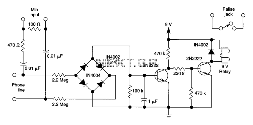
The DC voltage present on the telephone line typically ranges from 45 to 50V when on-hook and drops to approximately 6V when off-hook. This condition activates a step-down circuit relay, which in turn controls a tape recorder. Audio input...
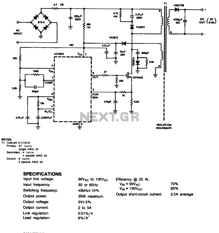
This circuit employs a cost-effective feedback scheme where the direct current voltage generated from the primary-side control winding is monitored by the UC1842 error amplifier. Consequently, load regulation is influenced by the coupling between the secondary and control windings,...
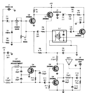
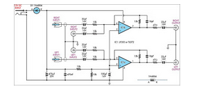
A simple TV audio-video transmitter circuit can be constructed using this schematic diagram. This circuit allows for the transmission of video signals from a VCR or other devices to a TV without the need for cables. The video signals...
Many Video Operated Relay (VOR) circuits have been published in recent years for use in connection with ATV repeater controllers or automatic videotape logging systems. Unfortunately, many of these circuits fail to properly detect certain video signals depending on...

A compact, inexpensive and low component count telecom headset can be constructed using two readily available transistors and a few other electronic components. This circuit is very useful for hands-free operation of EPABX and pager communication. Since the circuit...
Warning: include(partials/cookie-banner.php): Failed to open stream: Permission denied in /var/www/html/nextgr/view-circuit.php on line 713
Warning: include(): Failed opening 'partials/cookie-banner.php' for inclusion (include_path='.:/usr/share/php') in /var/www/html/nextgr/view-circuit.php on line 713