
Video-signal-clamp
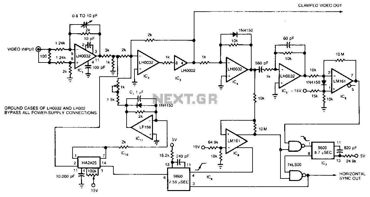
The circuit utilizes a track-and-hold amplifier in a closed-loop configuration to clamp the back-porch voltage of a standard video waveform to 0 V. The outputs of the circuit include a clamped composite video signal and a TTL-level horizontal blanking pulse. Differential input buffer IC1 and summing amplifier IC2 serve to isolate the input video signal. Clipper IC4 removes the video signal, retaining only the synchronization information. Differentiator IC5 detects the edges of the horizontal blanking pulses and generates pulses that correspond to the leading and trailing edges of these pulses. IC6 clips these pulses and converts them to a TTL level. IC7 utilizes these clipped pulses to create a TTL-level window that, when combined with the horizontal pulse generated by IC8, produces a TTL representation of the original horizontal pulse, synchronized to the input waveform. IC9 employs the trailing edge of this reconstructed waveform to generate the track pulse for track-and-hold amplifier IC10. Finally, IC11 filters the output of IC10 and, after gain adjustment, feeds it back to the summing node of IC2.
The circuit architecture is designed for precise video signal processing, particularly in applications requiring synchronization and signal integrity. The track-and-hold amplifier, IC10, is crucial for capturing the instantaneous voltage of the video signal at specific intervals, enabling the clamping of the back-porch voltage to 0 V. This ensures that the video signal remains within the acceptable voltage levels for further processing.
The differential input buffer, IC1, plays a significant role in preventing loading effects that could distort the input video signal. By isolating the input, it maintains signal integrity before it reaches the summing amplifier, IC2. The summing amplifier combines the clamped video signal with other necessary components, ensuring that the output remains a faithful representation of the original input.
Clipper IC4 is utilized to eliminate the video information while preserving the synchronization pulses, which are essential for timing in video applications. The differentiator IC5 is responsible for detecting the transitions in the horizontal blanking interval, generating sharp pulses that mark the leading and trailing edges. These pulses are then processed by IC6, which clips them to TTL levels, ensuring compatibility with digital logic circuits.
IC7 is tasked with creating a TTL-level window that works in conjunction with the horizontal pulse from IC8. This step is vital for achieving synchronization with the original waveform, allowing for accurate timing in video signal processing. The reconstructed horizontal pulse is then used by IC9 to generate the track pulse for the track-and-hold amplifier, ensuring that the right information is captured at the correct moment.
Finally, IC11 acts as a filter for the output of IC10, smoothing any variations and adjusting the gain before sending the processed signal back to the summing node of IC2. This feedback loop is essential for maintaining the stability and accuracy of the output signal, ensuring that the circuit operates effectively in a variety of video signal processing applications. Overall, this circuit design exemplifies a sophisticated approach to handling and processing video signals while maintaining synchronization and signal fidelity.The circuit uses a track-and-hold amplifier in a closed-loop configuration to clamp the back-porch voltage of a standard video waveform to 0 V. The circuit"s outputs include a clamped composite-video signal and a TTL-level horizontal-blanking pulse.
Differential input buffer IC1 and the summing amplifier IC2 isolate the input video signal. Clipper I C4 removes the video signal, leaving only the synchronization information. Differentiator IC5 detects the edges of the horizontal blanking pulses and produces pulses that correspond to the leading and trailing edges of the horizontal blanking pulses. IC6 clips these pulses and converts them to a TTL leveL IC7 uses these clipped pulses to generate a TTL-level window that, when combined with the horizontal pulse generated by IC8, forms a TTL representation of the original horizontal pulse. This representation is synchronized to the input waveform. IC9 uses the trailing edge of this reconstructed waveform to generate the track pulse for track-and-hold amplifier IC1O.
IC1l filters IClO"s de output and, after gain adjustment, feeds it back to IC2"s summing node. 🔗 External reference