
Video Stabilizer circuit
The circuit described is designed to bypass MacroVision copy protection found in VHS tapes, allowing for the creation of legal backup copies without the distortion typically introduced by this protection scheme. It operates with both NTSC and PAL video formats, which is essential for compatibility with various video sources.
The circuit comprises multiple resistors, capacitors, diodes, transistors, and integrated circuits (ICs) that work together to process the incoming composite video signal. Key components include:
- **Resistors**: Various resistors, such as R1 to R5 (68K), R6 (75 Ohm), and others, are used to set biasing levels, form voltage dividers, and limit current through the circuit.
- **Capacitors**: Capacitors like C1 (15uF) and C2 (220uF) are utilized for filtering and coupling, ensuring that the video signal remains stable and free of noise.
- **Diodes**: A series of 1N4148 diodes are employed for signal rectification and protection against voltage spikes.
- **Transistors**: The BC548 (NPN) and BC558 (PNP) transistors are used for amplifying signals and switching operations within the circuit.
- **Integrated Circuits**: The 4040 ripple counter and 4027 dual J-K flip-flops play critical roles in timing and control functions, enabling the circuit to accurately interpret and modify the video signal. The 4011 NAND gate and TL802 op-amp are used for logical operations and signal processing, while the 4053 multiplexer routes the video signals appropriately.
- **Jumpers**: The circuit includes multiple jumpers (J1-J9, J10-J18, J19-J27) that must be configured based on the type of MacroVision protection being bypassed. The user must manually set these jumpers according to the specified upper and lower line numbers for PAL or NTSC formats.
To operate the circuit, the user must connect the video source to the "Composite Video In" jack. The output is available at the "Composite Video Out" jack, providing a corrected video signal free from MacroVision interference. The circuit can pass the video signal unmodified when the "Video" terminals are disconnected, allowing for normal operation when MacroVision removal is not needed.
For correct functionality, it is crucial to ensure that all unused inputs of the CMOS ICs are tied to ground, as this will prevent floating inputs that could lead to erratic behavior. The circuit is powered by a 12V supply, which is standard for many video processing applications.
Overall, this circuit provides a practical solution for users seeking to create legal copies of their video content without the hindrance of MacroVision protection. Proper assembly and configuration are essential for achieving optimal performance.Have you ever attempted to copy a commercially produced video only to end up with a distorted and jumpy image? If so, then you have run afoul of MacroVision. MacroVision is the most popular copy protection scheme used on the majority of content distributed on VHS cassettes.
Like all copy protection, it does nothing to discourage the real pirates and only annoys the user who may wish to create a legal copy for backup and archival purposes. This circuit can eliminate MacroVision encoding in both NTSC and PAL recordings. R1, R2, R3, R4, R5, R7 6 68K 1/4W Resistor R6 2 75 Ohm 1/4W Resistor R8, R9 2 100 Ohm 1/4W Resistor R10 1 2.2K 1/4W Resistor R11 1 1.5K 1/4W Resistor R12, R17 2 470K 1/4W Resistor R13, R16 2 33K 1/4W Resistor R14 1 6.8K 1/4W Resistor R15 1 22K 1/4W Resistor R18 1 47K 1/4W Resistor C1 1 15uF Electrolytic Capacitor C2 1 220uF Electrolytic Capacitor C3 1 220pF Ceramic Disc Capacitor C4 1 0.0022uF Ceramic Disc Capacitor C5, C7, C8, C9, C10, C11, C12, C13 7 0.1uF Ceramic Disc Capacitor C6 1 0.47uF Ceramic Disc Capacitor D1-D9, D10-D18, D19-D27, D28, D29, D30, D31, D32, D33, D34, D35 35 1N4148 Diode Q1 1 BC548 NPN Transistor Q2 1 BC558 PNP Transistor U1 1 4040 12-Bit Ripple Counter U2, U3 2 4027 Dual J-K Flip Flop U4 1 4011 Quad Two Input NAND Gate U5 1 TL802 Dual Op Amp U6 1 4053 Triple Two Channel Multiplexer U7 1 4069 Hex Inverter J1-J9, J10-J18, J19-J27 27 Jumper J28, J29 2 RCA Jack MISC 1 PC Board, Wire, Sockes For ICs Notes The circuit was submitted via email by Jari Ekstrom. Jari noted that the author is Antti Paarlahti and that the circuit originally came from the author's website.
This website is no longer accessible. However, some searching revealed that the author of the circuit also wrote The MacroVision FAQ. The email address listed for the author in the FAQ is invalid and the FAQ was last updated in late 1996. This circuit reproduced here without permission. Before use, the circuits's jumper need to be set. Take a look at the table below: MacroVision Type Upper Start Line Upper End Line Lower Start Line PAL 0x05 0x0F 0x126 NTSC 0x06 0x0E 0xFB To set the jumpers, first convert the line numbers to binary.
You will end up with three binary digits, one for each set of line numbers. Bit 0 is least significant, bit 8 is most significant. Now simply open the jumpers at the 0 bits and close the jumpers at the 1 bits. Connect your video source to "Composite Video In". As the label suggests, this circuit accempts composite video signals only. The corrected video signal is sent to the "Composite Video Out" jack. With the two "Video" terminals disconnected the circuit passes video through without modifying it. Jumping the "Video" terminals enables the MacroVision removal. As with all circuits involving CMOS (4000 series) ICs, you must tie the unused inputs of those ICs to ground. This is not shown on the schematic for clarity. Supply voltage is 12V. 🔗 External reference
Related Circuits

This circuit is a graphic equalizer that can be built with a low component count and is controlled using the LA3600 single IC chip. The internal design of the chip utilizes a transistor gyrator circuit, with connections to external...
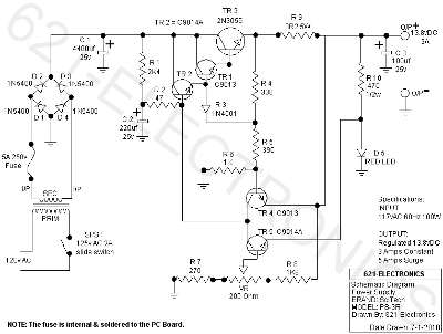
The following circuit illustrates the SciTech PS-3R Power Supply Circuit. Features include 13.8V DC output, 5 Amps surge capability, and a constant output of 3 Amps. Components include a transistor and others. The SciTech PS-3R Power Supply Circuit is designed...
The metal detector circuit consists of a probe oscillator, a PLL (phase-locked loop) circuit, and an audio alarm circuit. The probe oscillator includes a detection coil (L), transistor (V1), and several resistors (R1 to R3) and capacitors (C1 to...

The multi-purpose signal generator circuit consists of integrated circuit oscillators and frequency dividers. It generates square waves ranging from high frequencies to sub-audio frequencies and also produces a frequency standard in the VHF range. The alternative oscillator section feeds...
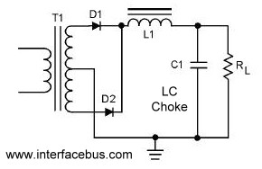
A circuit that utilizes both positive and negative alternations in an alternating current to generate direct current. There are two types of full-wave rectifier circuits: one that employs two diodes and requires a center-tapped transformer, and another that uses...
The FM front-end circuit, also referred to as an FM receiver circuit, is composed of discrete components. This configuration presents challenges in debugging and is prone to difficulties in miniaturization, leading to its gradual replacement by FM radio integrated...