
Visible-red-continuous-laser-gun
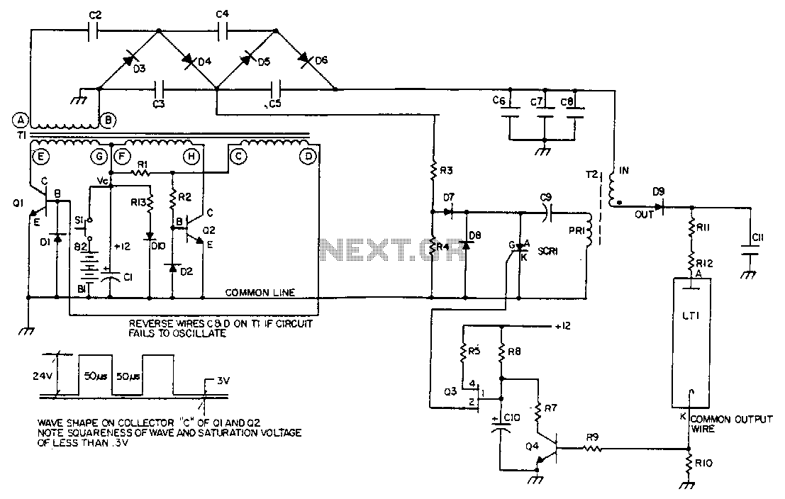
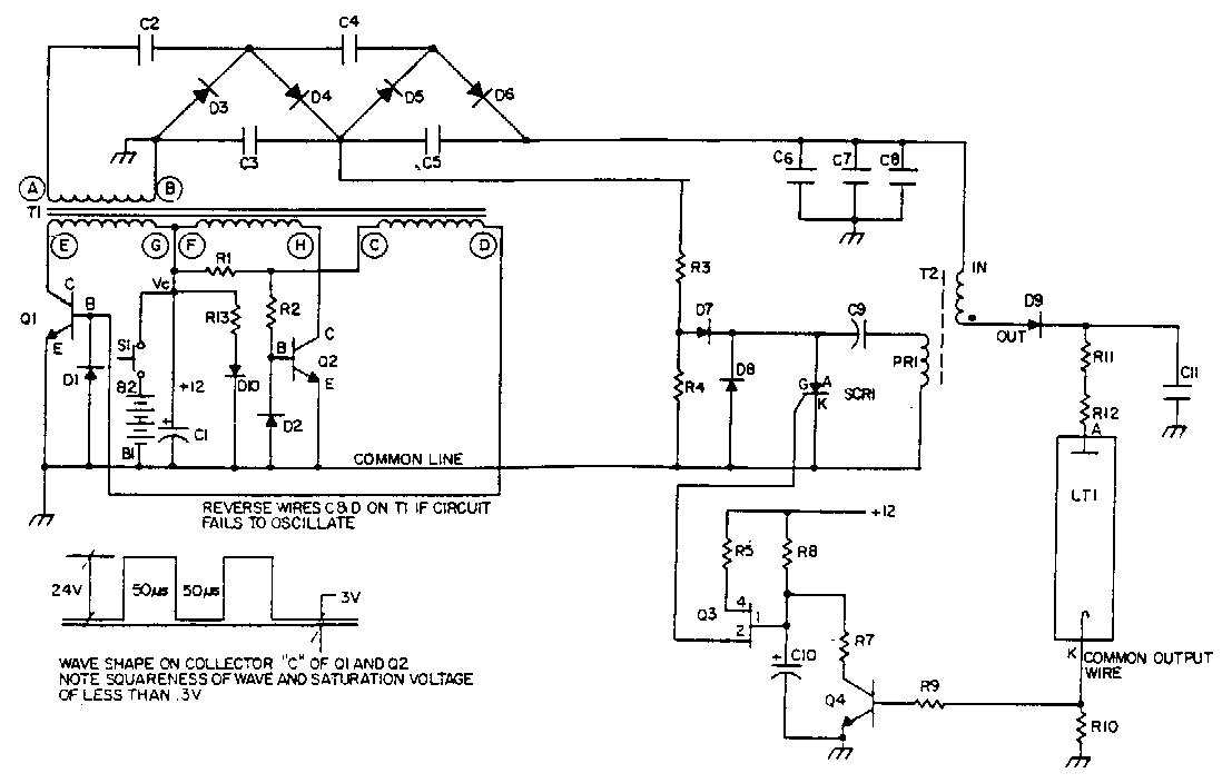
Q1 and Q2 control the primary windings of transformer T1 using a square wave at a frequency determined by the transformer's magnetic properties. Diodes D1 and D2 provide return paths for the feedback current of Q1 and Q2. The output winding of T1 is connected to a multi-section voltage multiplier, which consists of capacitors C1 through C5 and diodes D3 through D6. Resistors R3 and R4 divide the 800 V taken from the junction of C3 and C5 to charge the dump capacitor C9 in the ignitor circuit. The ignitor, which includes the T2 pulse transformer and capacitor discharge circuitry, generates a high-voltage pulse to ignite the laser by dumping the energy of capacitor C9 into the primary of T2. High-voltage pulses are stored in capacitor C11 and are rectified by diode D9. When C11 is charged to a certain threshold, ignition occurs, allowing a current flow sufficient to sustain itself at the lower voltage output of the voltage multiplier. This sustaining current flows through the secondary of T2 and ballast resistors R11 and R12. The ignitor circuit is deactivated by clamping the emitter of Q3 via Q4, which is triggered by the voltage drop across R10. This voltage drop occurs only when the laser tube is ignited, causing SCR1 to stop firing; otherwise, the ignitor circuit would continue to operate, unnecessarily consuming the limited available power.
The circuit described operates on a principle of high-voltage pulse generation and control for laser ignition. The primary stage involves the switching of Q1 and Q2, which form a push-pull configuration to drive the transformer T1. The square wave generated is critical for the efficient operation of the transformer, enabling it to step up the voltage to the levels required for laser ignition.
Diodes D1 and D2 serve a crucial role in providing necessary feedback to the base of the transistors, ensuring that they operate in a stable manner. The voltage multiplier, composed of capacitors C1 to C5 and diodes D3 to D6, is designed to accumulate voltage effectively, allowing the circuit to reach high voltages necessary for the ignitor. The resistors R3 and R4 are essential for voltage division and help manage the high voltage taken from the junction between capacitors C3 and C5, ensuring that the dump capacitor C9 receives the appropriate charge.
The ignitor circuit is particularly significant as it uses the T2 pulse transformer, which is tasked with transferring the energy stored in C9 to ignite the laser. The operation of SCR1 is pivotal; it acts as a switch that allows the energy from C9 to be dumped into T2. The resulting high-voltage pulse is stored in capacitor C11, which is monitored for a threshold voltage that indicates a successful ignition of the laser.
Once the laser is ignited, the circuit enters a self-sustaining mode, where current flows through the secondary of T2 and the ballast resistors R11 and R12. This self-sustaining operation is crucial for maintaining laser operation without continuous input from the ignitor circuit. The deactivation mechanism involving Q3 and Q4 ensures that the ignitor does not continue to draw power unnecessarily, which is critical in systems with limited power resources. The design effectively balances the need for high-voltage ignition with the management of power consumption, showcasing a well-thought-out approach to laser ignition circuitry.Ql and Q2 switch the primary windings of transformer Tl via a square wave at a frequency determined by its magnetic properties. Diodes Dl and D2 provide base return paths for the feedback current of Ql and Q2. The output winding of T1 is connected to a multiple section voltage multiplier. That multiplier consists of capacitors Cl through C5 and diodes D3 through D6. Resistors R3 and R4 divide the 800 V taken off at the junction of C3, and C5 for charging the dump capacitor C9 in the ignitor circuit.
The ignitor, consisting of the T2 pulse transformer and capacitor discharge circuitry, provides the high-voltage de pulse to ignite the laser the SCRl dumping the energy of capacitor C9 into the primary of T2. The high-voltage pulses in capacitor Cll through rectifier diode D9. When Cll is charged to a LTl, ignition takes place and a current now flows that is sufficient to sustain itself at the lower voltage output of the voltage multiplier section.
The path for this sustaining current is through the secondary of T2 and ballast resistors Rll and Rl2. The ignitor circuit is now deactivated by the clamping of Q3 emitter via Q4 being turned on by the voltage drop occurring across Rl0.
This voltage drop will only occur when the laser tube is ignited and causes the SCRl to cease firing; otherwise, the ignitor circuit would continue to operate, unnecessarily drawing on the limited power available. 🔗 External reference
Related Circuits
Q1 and Q2 control the primary windings of transformer T1 using a square wave signal, the frequency of which is determined by the magnetic properties of the transformer. Diodes D1 and D2 serve as base return paths for the...
Warning: include(partials/cookie-banner.php): Failed to open stream: Permission denied in /var/www/html/nextgr/view-circuit.php on line 713
Warning: include(): Failed opening 'partials/cookie-banner.php' for inclusion (include_path='.:/usr/share/php') in /var/www/html/nextgr/view-circuit.php on line 713