
Visual Continuity Tester Circuit
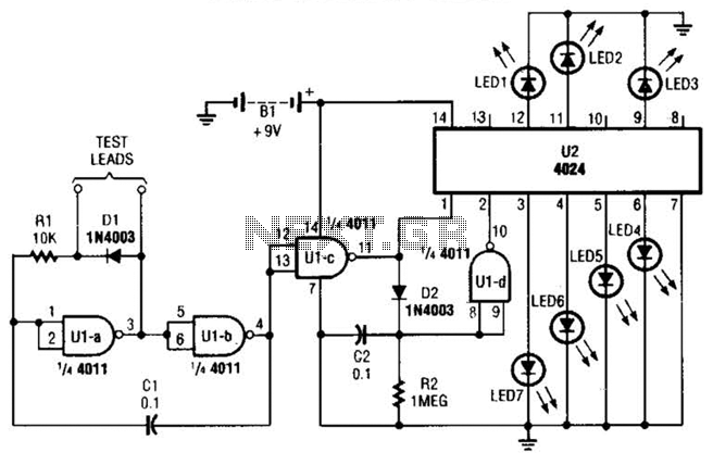
The output from the oscillator is directed to pins 12 and 13 of U1-c, which then splits into two pathways. In the first pathway, the output of U1-c is connected to the clock input of U2 (the 4024 binary counter) at pin 1. In the second pathway, the signal passes through diode D2 and charges capacitor C2. The voltage across C2 is applied to U1-d at pins 8 and 9. The output from this inverter (U1-d) is connected to the reset terminal (pin 2) of U2. If there is continuity or measurable resistance between the test probes, the reset terminal of U2 is pulled low, triggering the counter to process the input pulses (count). The counting rate is proportional to the resistance between the probes. If the resistance is low, the counter increments slowly. The counter outputs a 7-bit binary signal, which is connected to seven LEDs. When the test probes are across a short circuit, LED7 flashes. For a resistance of, for example, 2 ohms, LED1 will flash. In both scenarios, the LED corresponding to the resistance value closest to that between the probes will flash steadily, while the other LEDs will appear to flash intermittently.
The circuit operates on the principle of a variable frequency oscillator, where the frequency is modulated by the resistance detected. The astable multivibrator configuration allows for continuous oscillation, with the frequency determined by the RC time constant formed by R1 and the unknown resistance. The output of the oscillator is crucial for driving the binary counter, which counts the oscillations and translates them into a binary number. This number is then displayed on the LEDs, providing a visual indication of the resistance value.
The use of a binary counter allows for precise counting and representation of the resistance, while the LEDs serve as a user-friendly interface. The design ensures that even small changes in resistance can be detected and displayed, making the circuit effective for various applications, including basic resistance measurement and continuity testing. The circuit is compact and can be implemented on a breadboard or PCB for practical use in electronics testing and diagnostics. By judging the rate at which a particular LED flashes, you`ll be able to estimate the resistance. The circuit consists of two IC`s (1 4011 CMOS quad 2-input, NAND gate, Ul; and a 4024 binary counter, U2), seven LEDs, and a handful of additional .components. All of the gates in Ul are wired as inverters. Two of the inverters (Ul-a and Ul-b) comprise an astable-multivibrator (free-running oscillator) circuit, whose operating frequency depends on the amount of resistance detected between the test probes.
Feedback from the output of the oscillator (at pin 4 of Ul-b) back to the input of the circuit (at Ul-a, pins 1 and 2) is provided via CI. Resistor, Rl, along with the unknown resistance between the test probes, completes the RC timing circuit.
The frequency of the oscillator decreases as the resistance between the test probes increases. The output of the oscillator is fed to pin 12 and 13 of Ul-c, the output of which then divides along two paths. In the first path, Ul-c`s output is applied to the clock input of U2 (a 4024 binary counter) at pin 1; in the other path, the signal is fed through D2 and across capacitor C2, causing it to begin charging.
The charge on C2 is applied to Ul-d at pins 8 and 9. The output of that inverter (Ul-d) is fed to the reset terminal (pin 2) Of U2. If there is continuity or a measurable resistance between the test probes, U2`s reset terminal is pulled low, triggering the counter and allowing it to process the input pulses (count). The rate of the count is proportional to the resistance between the test probes. If the resistance between the test probes is low, the counter advances slowly. The counter provides a 7-bit binary output that is wired to seven LEDs. When the test probes are placed across a short circuit, LED7 flashes. If the tester is placed across a resistance of, for example, 2, LED1 will flash. In either case, the LED whose assigned value most closely corresponds to the resistance connected between the two probes will flash continually at a steady pace, while the other LEDs will seem to flash intermittently.
🔗 External reference
Related Circuits
This DC to DC converter increases a DC voltage to nearly double its original value and is useful for elevating the output voltage of solar batteries to the required level. The DC to DC converter operates on the principle of...
Many amateur receivers are equipped with an S meter that does not operate logarithmically. The proposed circuit is intended to enhance such receivers. Although integrated circuits like the CA3089 or CA3189 are not commonly used today, they play a...
An RF field indicator is needed to verify power stages and transmitter antennas. This radio field indicator allows for the measurement of radiated energy from antennas. An RF field indicator is a crucial device in the field of telecommunications and...
An inverter is introduced which primarily utilizes a MOS field-effect transistor in conjunction with a conventional power transformer. The output power of the inverter is determined by the specifications of both the MOS field-effect transistor and the transformer, thereby...
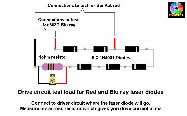
A guide will be posted on how to test a DDL circuit before integrating the LD. The process aims to ensure clarity and accuracy throughout. To properly test a DDL (Direct Drive Laser) circuit before adding the LD (Laser Diode),...
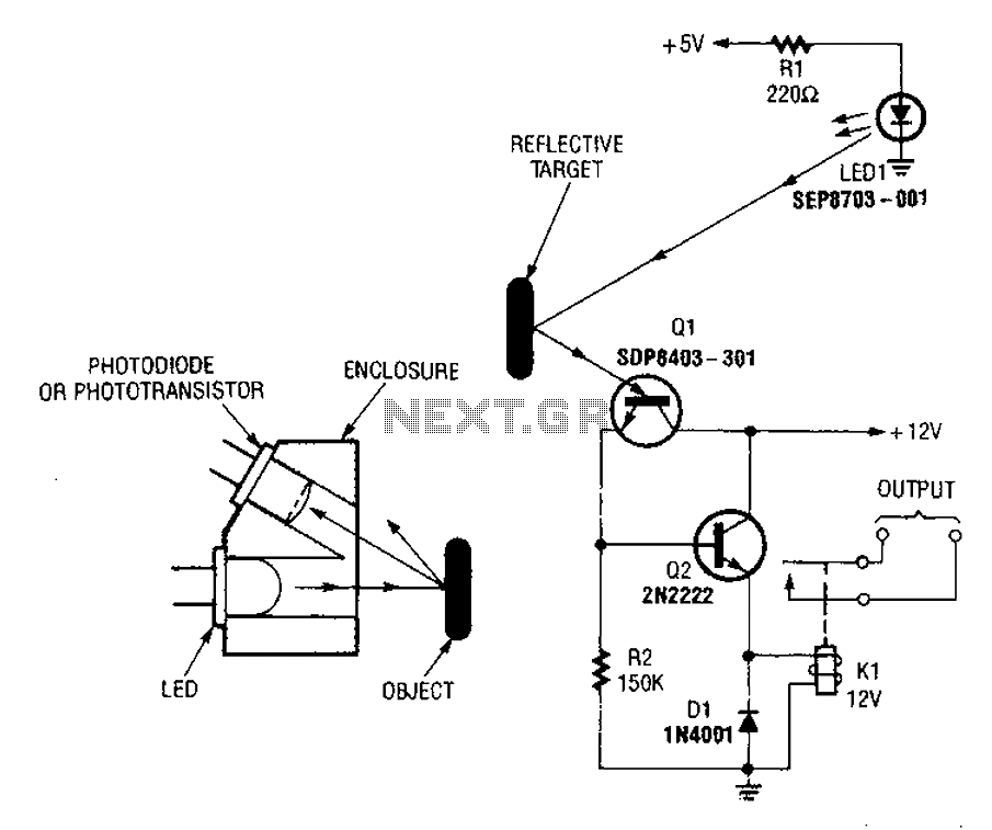
A reflex isolator detects the presence of an object by reflecting light from the object back to the sensor. This technique is effective when an object is in close proximity to the sensor. Reflex isolators, also known as proximity sensors,...