
Voltage Comparators

The circuit utilizes two operational amplifiers configured as comparators to monitor voltage levels. The first comparator is designed to detect over-voltage conditions. When the input voltage (Vm) surpasses a predetermined reference voltage, the output of the first operational amplifier (IC1) transitions to a low state, indicating that the voltage level is too high. This output can be used to trigger additional circuits, such as an alarm or a shutdown mechanism, to protect sensitive components from damage due to excessive voltage.
In the second comparator configuration, the circuit monitors for under-voltage conditions. When the input voltage (ViN) exceeds the reference voltage, the output voltage (Vout) of the second operational amplifier transitions to a high state. This indicates that the input voltage has reached a level that is acceptable and can be safely processed by downstream components. The high output can also activate additional circuitry, such as enabling power to a load or signaling that the system is operating within safe voltage parameters.
Overall, these comparator circuits are integral in ensuring that voltage levels remain within specified limits, providing critical protection and operational assurance in various electronic applications. Their design can be adapted to suit different voltage thresholds and applications, making them versatile components in voltage monitoring systems. These two comparators are over- and under-voltage comparators. In Fig. 104-5(a), if Vm exceeds the reference voltage, t he output of IC1 goes low. In Fig. 104-5(b), if the ViN exceeds the reference, Vout goes high. 🔗 External reference
Related Circuits
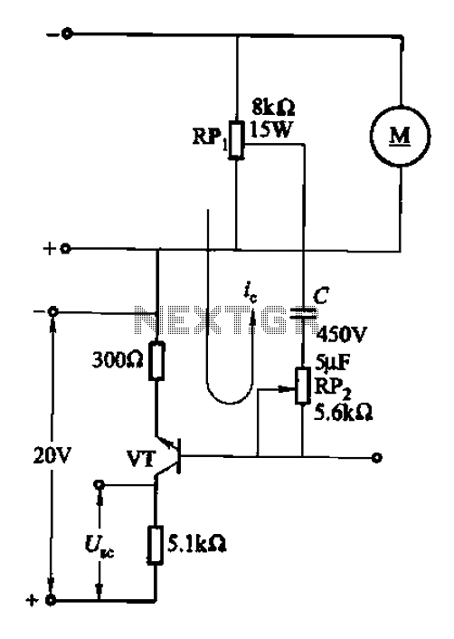
After integrating the negative feedback circuit, the adjustment object and inertial measurement feedback link are susceptible to oscillations. To address this, a voltage differential or speed differential circuit is employed to minimize or eliminate these oscillations, serving as a...
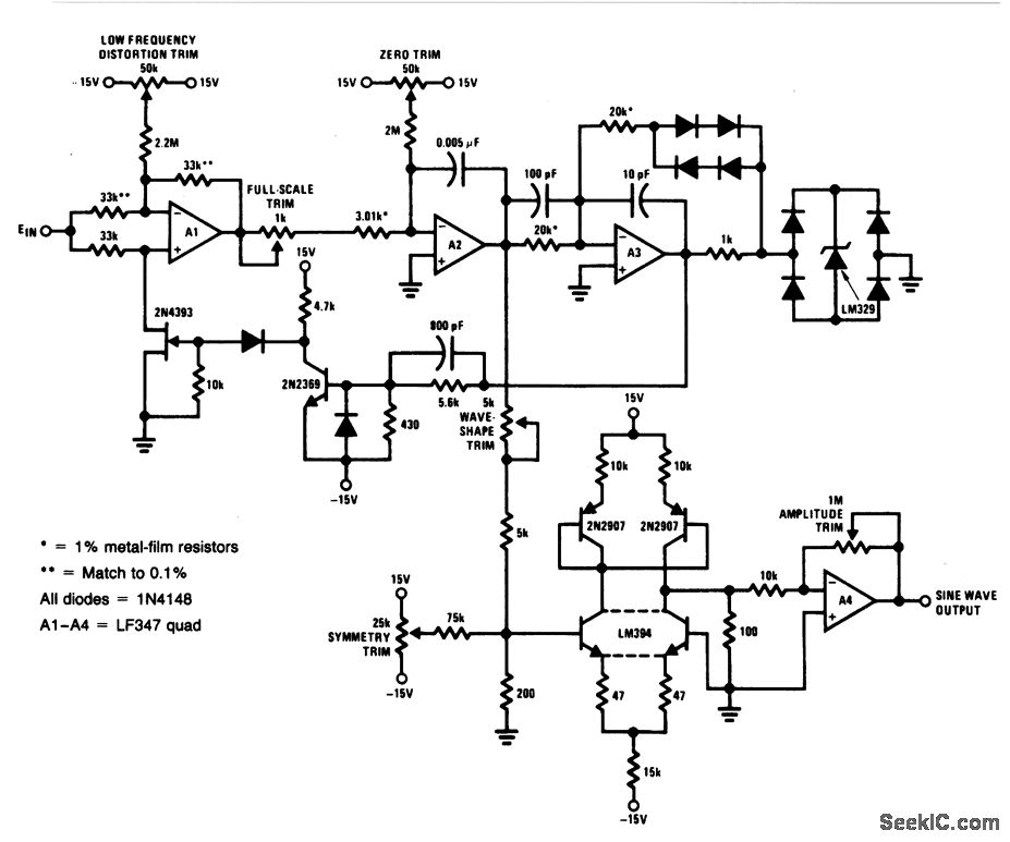
For a 0- to 10-V input, this circuit generates sine-wave outputs ranging from 1 Hz to 20 kHz, achieving linearity better than 0.2%. The distortion level is approximately 0.4%, and both the frequency and amplitude of the sine-wave output...
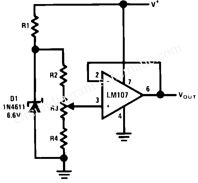
The circuit is designed for high precision operation over an extended temperature range, provided that V+ remains relatively constant, as the current IZ is dependent on V+. Resistors R1, R2, R3, and R4 are selected to ensure the appropriate...
Gain adjustment can be made more flexible when controlled by a voltage signal, as this allows for various methods to provide a user interface. The concept of voltage-controlled gain adjustment is integral to many electronic circuits, particularly in audio processing...
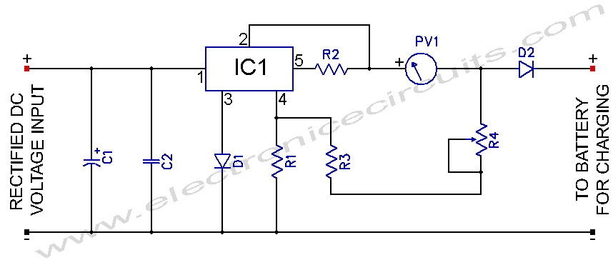
L200 12V Constant Voltage Battery Charger Circuit. This battery charger is based on the L200 regulator IC. The L200 is a five-pin adjustable voltage regulator. The L200 constant voltage battery charger circuit is designed to provide a stable 12V output...
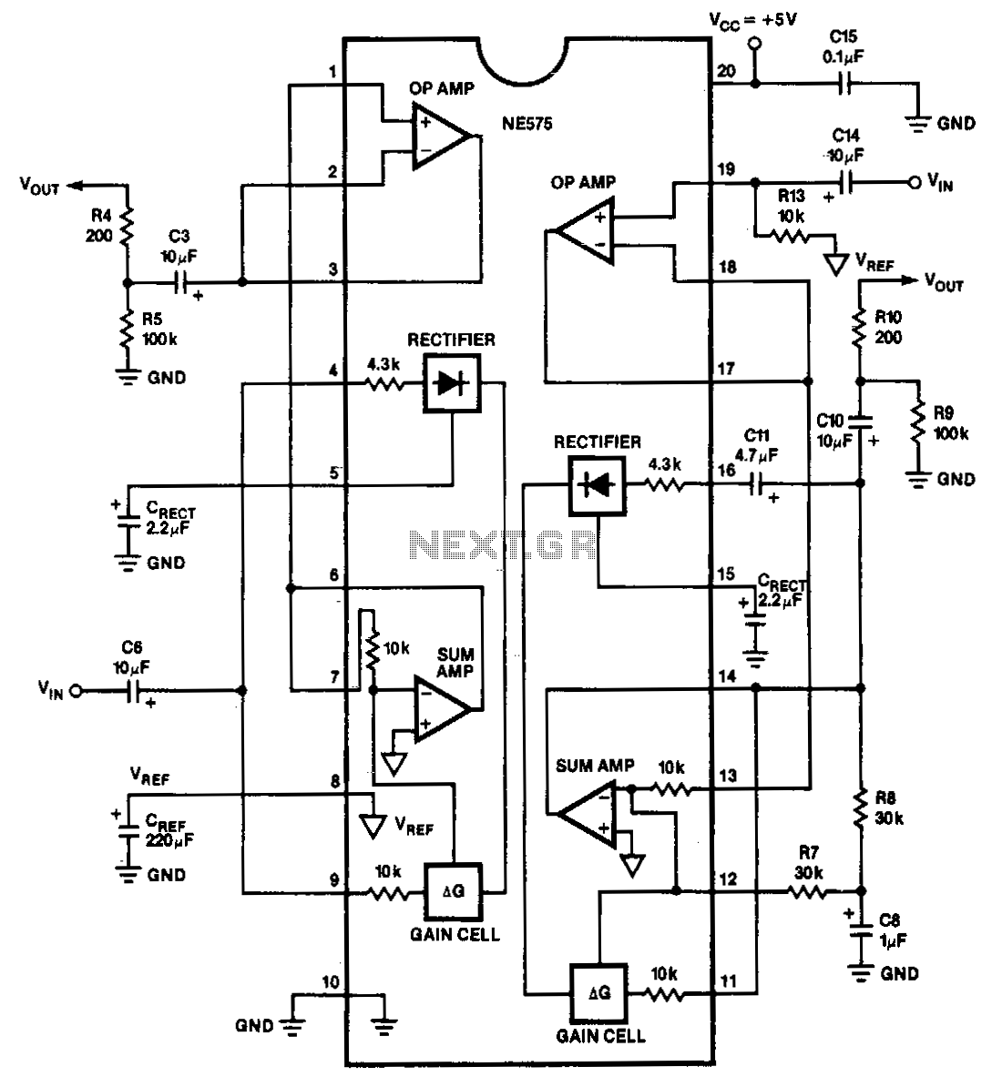
The NE575 is a dual-gain control circuit designed for low voltage applications. Channel 1 acts as an expander, while Channel 2 can be configured for expander, compressor, or automatic level controller (ALC) applications. The NE575 dual-gain control circuit is specifically...
Warning: include(partials/cookie-banner.php): Failed to open stream: Permission denied in /var/www/html/nextgr/view-circuit.php on line 713
Warning: include(): Failed opening 'partials/cookie-banner.php' for inclusion (include_path='.:/usr/share/php') in /var/www/html/nextgr/view-circuit.php on line 713