
Voltage-controlled-crystal-oscillator
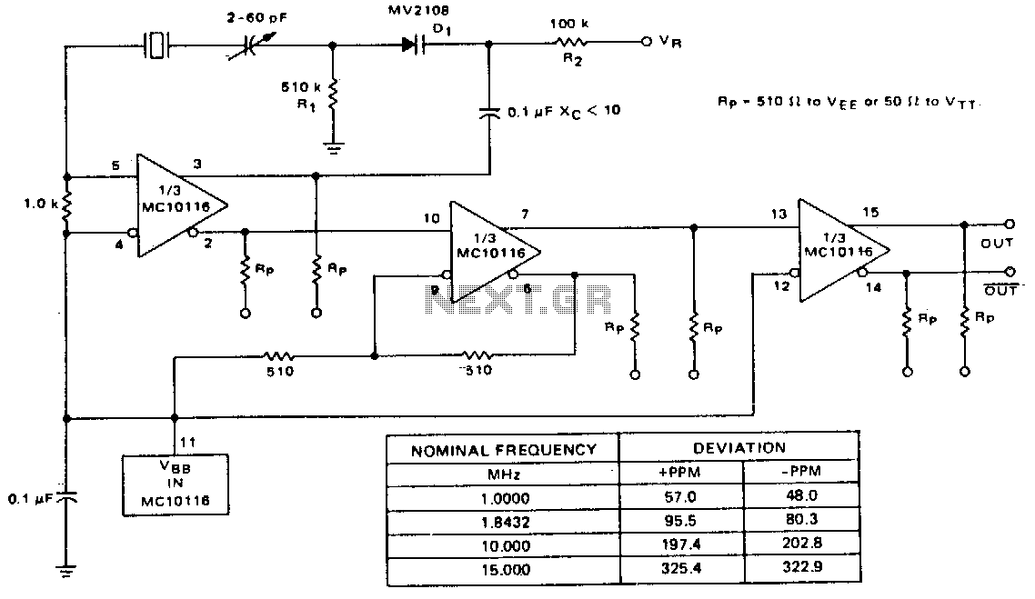
A voltage-variable capacitance tuning diode is connected in series with the crystal feedback path. Adjusting the voltage on the variable resistor (VR) changes the capacitance of the tuning diode, which in turn tunes the oscillator. The 510 kΩ resistor (R1) establishes a reference voltage for VR, with ground used as the reference in this example. A 100 kΩ resistor (R2) isolates the tuning voltage from the feedback loop, while a 0.1 µF capacitor (C2) provides AC coupling to the tuning diode. The circuit operates over a tuning range of 0 to 25 V. The tuning range can be reversed by switching the orientation of the tuning diode (D1). The center frequency is adjusted using a 2-60 pF trimmer capacitor. The deviation from the center frequency is dependent on the crystal frequency, with a table in Fig. 21-7 displaying the measured deviation in parts per million for several tested crystals.
The circuit utilizes a voltage-variable capacitance tuning diode, which allows for precise frequency adjustments in oscillator circuits. The tuning diode's capacitance is directly influenced by the voltage applied through the variable resistor (VR), enabling fine-tuning of the oscillator frequency. The configuration employs a 510 kΩ resistor (R1) to set a stable reference voltage for the variable resistor, ensuring consistent tuning performance.
In addition, a 100 kΩ resistor (R2) serves to isolate the tuning voltage from the feedback loop, preventing any unwanted interactions that could affect the oscillator's stability. The 0.1 µF capacitor (C2) is crucial for AC coupling, allowing the high-frequency signals to pass while blocking any DC components that could interfere with the tuning process.
The tuning range of 0 to 25 V provides flexibility in application, and reversing the orientation of the tuning diode (D1) allows for adjustment of this range, catering to different circuit designs or operational requirements. The center frequency of the oscillator is fine-tuned with a 2-60 pF trimmer capacitor, which adjusts the capacitance in the circuit and allows for precise control over the output frequency.
The relationship between the oscillator's frequency deviation and the crystal frequency is significant, as indicated by the data presented in the referenced table (Fig. 21-7). This table quantifies the frequency deviation in parts per million (ppm) for various tested crystals, providing insight into the performance and reliability of the tuning circuit across different crystal types. This information is essential for engineers when selecting components for specific applications, ensuring that the oscillator meets the desired frequency stability and accuracy requirements.A voltage-variable capacitance tuning diode is placed in series with the crystal feedback path. Changing the voltage on VR varies the luning diode capacitance and tunes the oscillator. The 510-KO resistor, R1, establishes a reference voltage for VR -ground is used in this example. A 100-KO resistor, R2, isolates the tuning voltage from the feedback loop and 0.1-I"F capacitor C2 provides ac coupling to the tuning diode. The circuit operates over a tuning range of 0 to 25 V. It is possible to change the tuning range from 0 to 25 V by reversing the tuning diode D 1. Center frequency is set with the 2 -60 pf trimmer capacitor. Deviation on either side of center is a function of the crystal frequency. The table in Fig. 21-7 shows measured deviation in parts per million for several tested crystals. 🔗 External reference