
Voltage-Controlled Current Source Uses Two Op Amps

The circuit described by Mazi Hosseini utilizes two operational amplifiers (op-amps) to create a voltage-controlled current source, which is an essential component in various electronic applications. The design aims to maintain a low-cost implementation while delivering a significant range of output current and accommodating maximum load requirements.
The first op-amp in the configuration is employed as a voltage follower, ensuring that the input voltage is accurately tracked without introducing any loading effects. This configuration allows the circuit to respond dynamically to changes in the input voltage, which directly influences the output current.
The second op-amp is configured in a feedback loop, where it regulates the output current based on the reference voltage provided at its non-inverting input. By manipulating the feedback resistor values, the desired output current can be finely tuned, enabling the circuit to provide a broad range of current levels suitable for various applications.
To enhance performance, the circuit may incorporate additional components such as resistors and capacitors to stabilize the op-amps and filter any noise present in the signal. Proper selection of these components is critical to achieving a reliable and efficient voltage-controlled current source.
Overall, this design represents an effective solution for applications requiring precise control of current with minimal cost, making it a valuable addition to the toolkit of electronic engineers and hobbyists alike.Author Mazi Hosseini describes a simple, low-cost, voltage-controlled current source using two op amps that provides a good range of current and maximum load 🔗 External reference
Related Circuits
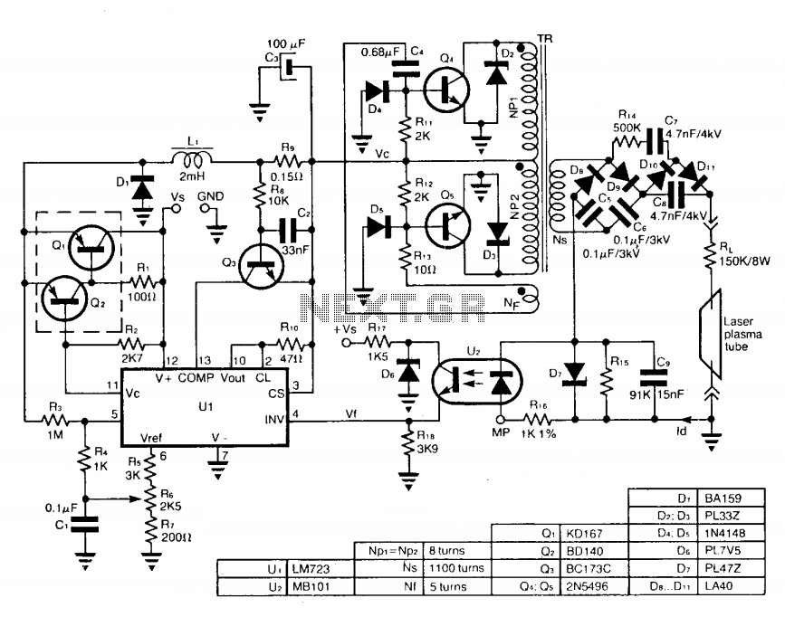
The circuit employs a free-running push-pull DC to DC high voltage converter to generate the required voltage for the laser plasma tube supply. The supply voltage (Vc) of this converter is regulated by a switch-mode power supply to maintain...
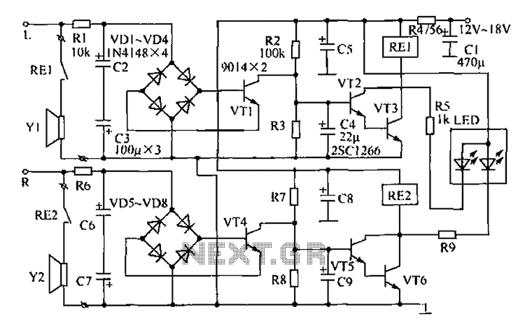
The speaker protection circuitry is designed for independent operation of the left and right channels. The left channel is exemplified by components R2, C4, and the VT2, VT3 configuration, which includes a start delay circuit to prevent power surges...
The designer requires a 1-Wire host computer IO framework that operates at 1.8V. Most 1-Wire devices are unable to function at this voltage. This application recommends implementing a 1.8V 1-Wire host computer alongside a 5V 1-Wire reference design for...
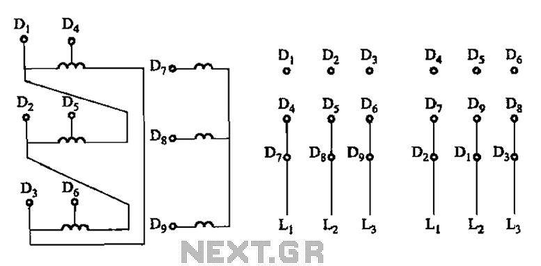
The connection of the lead wires from the stator winding of a two-speed motor to the coils is illustrated in Figure 3-109. The schematic representation of the two-speed motor's stator winding connection is critical for understanding its operational characteristics. In...
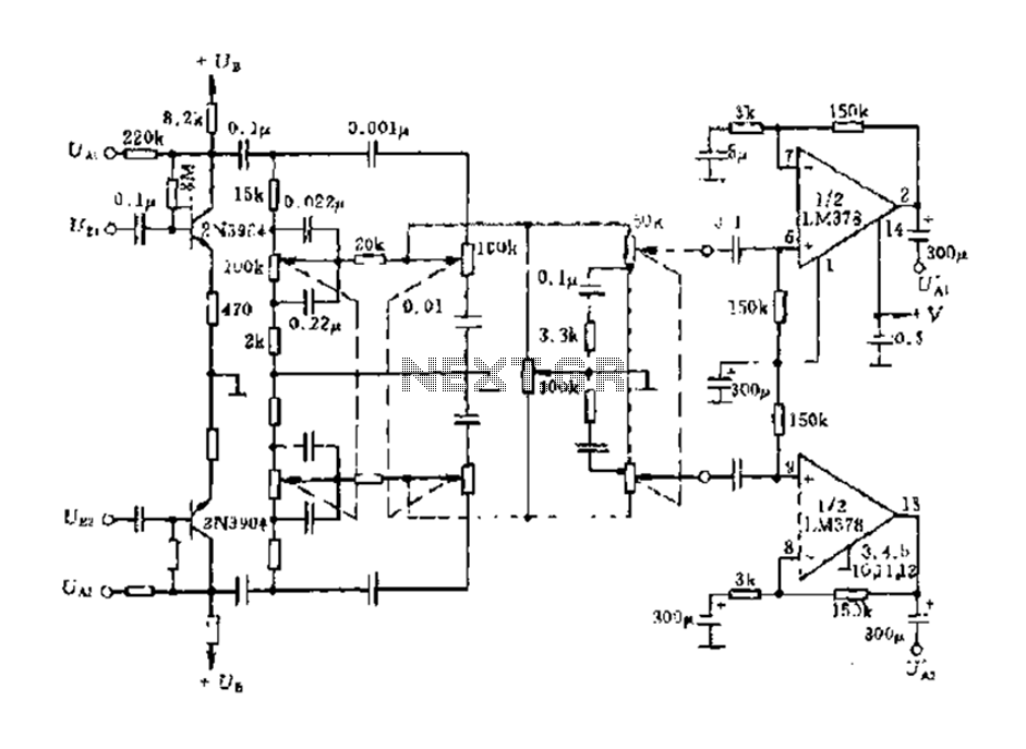
The dual-channel circuit features the LM378 dual operational amplifier and operates with a supply voltage of 24V, supporting an 8-ohm load (or 16 ohms). Each channel delivers an output power of 4W. The circuit includes internal current limiting and...
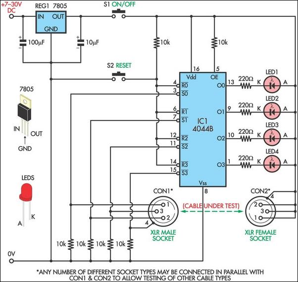
This circuit is designed to facilitate the testing of microphone cables or other types of cables for intermittent breaks that are often challenging to detect with a multimeter. The circuit can accommodate cables with up to four cores. It...