
Voltage-controlled-filter
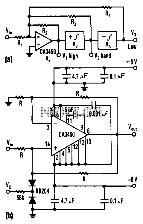
The control voltage Vc effectively adjusts the cutoff frequency w0 of this state-variable filter to any desired value, ranging from approximately 1.7 MHz to 5 MHz, using a BB 204 varicap and a resistance of 100 kΩ. Vc can vary from 0 to 28 V, which alters the capacitance of the varicap from about 4 pF to 12 pF. The circuit comprises an input summing circuit (A1) and two non-inverting integrators (A2 and A3). All three circuits utilize CA3450 operational amplifiers. With these components, cutoff frequencies of up to 200 MHz can be achieved. The circuit's cutoff frequency, Q-factor, and gain G can be expressed as follows: w0 = 2/CR, Q = R/R4, and G = R4/R1. For a fixed value of R4, such as 10 kΩ, the Q-factor is solely dependent on the resistance of R3. The Q-factor can reach any value, including 100, independently of both w0 and G. Likewise, the gain depends only on the resistance of R1 and can also be set as high as 100.
The state-variable filter described operates by utilizing a control voltage to dynamically set its cutoff frequency, which is a critical feature for applications requiring precise frequency management. The BB 204 varicap diode plays a crucial role in this configuration, as its variable capacitance allows for fine-tuning of the filter's response. The operational amplifiers CA3450 are selected for their high performance, enabling the circuit to handle high-frequency signals effectively.
The input summing circuit (A1) combines multiple input signals, ensuring that the output is a weighted sum of these inputs, which is essential for the filter's operation. The two non-inverting integrators (A2 and A3) are responsible for providing the necessary phase shift and gain to shape the filter's frequency response. The circuit's design allows for significant flexibility in tuning the Q-factor, which influences the selectivity and bandwidth of the filter. The ability to set the Q-factor independently from the cutoff frequency and gain is particularly advantageous in applications where precise control over the filter characteristics is needed.
In practical applications, the ability to achieve cutoff frequencies up to 200 MHz makes this filter suitable for a variety of high-frequency signal processing tasks, such as in communication systems or audio processing. The straightforward relationships defined for w0, Q, and G allow for easy calculations and adjustments during the design phase, facilitating efficient implementation in real-world scenarios. This design exemplifies a robust approach to state-variable filtering, providing both versatility and precision in electronic circuit applications.The control voltage Vc easily sets the cutoff frequency w0 of this state-variable filter to any desired value, from about 1.7 MHz up to 5 MHz, with a BB 204 varicap and R = 100 KO. Vc can range from 0 to 28 V. This range changes the capacitance of the varicap from about 4 to 12 pF. The circuit consists of input summing circuit A1 and two noninverting integrators, A2 and A3. Both the integrators and the summing-amplifier circuits use CA3450 op amps. With them, cutoff frequencies up to 200 MHz are possible. The circuit"s cutoff frequency, it"s Q-factor, and gain G are simply: w0 = 2/CR, Q = R,!R4, and G = R4/R1 For a given value for R4, say 10 KO, Q depends only upon the resistance of R3. The Q can be any value, even 100, independently of both w0 and G. Similarly, the gain then depends only on the resistance of R1 and can also be set as high as 100. 🔗 External reference
Warning: include(partials/cookie-banner.php): Failed to open stream: Permission denied in /var/www/html/nextgr/view-circuit.php on line 713
Warning: include(): Failed opening 'partials/cookie-banner.php' for inclusion (include_path='.:/usr/share/php') in /var/www/html/nextgr/view-circuit.php on line 713