
voltage How can I make LEDs light up equally
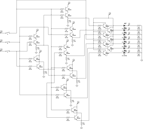
In this circuit, three binary switches are employed to represent values ranging from 0 to 7 (000 to 111 in binary). Each unique combination of the switches will activate a specific number of light-emitting diodes (LEDs) corresponding to the binary value represented by the switches. The challenge lies in ensuring that all LEDs receive an equal amount of current and voltage, which is essential for achieving uniform brightness across all activated LEDs.
To achieve this, a current-limiting resistor must be placed in series with each LED to prevent excessive current from flowing through them, which can lead to uneven brightness and potential damage. The value of this resistor can be calculated using Ohm's Law (V = IR), where V is the voltage drop across the LED, I is the desired current through the LED, and R is the resistance. The forward voltage drop of the LED, typically around 2V for standard red LEDs, should be considered when calculating the resistor value.
Additionally, a common approach to ensure that the LEDs light up with equal intensity is to use a constant current source. This can be achieved with a simple transistor-based circuit or a dedicated LED driver IC that regulates the current flowing through the LEDs, regardless of the number of LEDs activated.
In the proposed design, when a switch is closed, it completes a circuit that allows current to flow through the corresponding LED(s) and their associated resistors. The arrangement should ensure that no more than three LEDs are lit at any one time, which simplifies the design of the current-limiting resistors.
It is also advisable to use a microcontroller or a logic circuit to interpret the switch states and control the LEDs accordingly. This approach allows for more flexibility in managing the LED states and can help to simplify the circuitry by centralizing the control logic.
In summary, the successful implementation of this circuit requires careful consideration of the electrical characteristics of the LEDs, the use of current-limiting resistors, and possibly the integration of a constant current source to maintain uniform brightness across all LEDs, regardless of the binary combination represented by the switches.There are three switches that represent "binary number", and according to that switches` combination, number of lit LEDs change to represent that binary number. I am wondering how do provide equal current and voltage for LEDs and make them light up with equal luminous intensity independent of switches` combination.
Probably I`m not understanding s ome major law in electronics. 🔗 External reference
Related Circuits
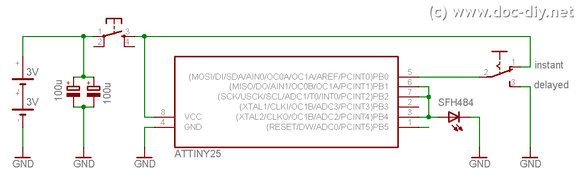
This site explains the process of constructing a low-cost DIY Canon RC-1 infrared remote control clone utilizing an AVR microcontroller. The project involves creating a remote control that mimics the functionality of the Canon RC-1, which is used for triggering...
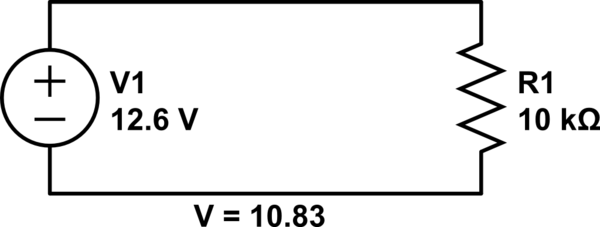
Connect a 12V fan to this circuit that consumes 70mA (0.07A), ensuring the circuit can supply at least that amount of current. There appears to be a misunderstanding regarding the analysis. The voltage drop across the resistor equals the...
This circuit is permanently connected to a mains socket and is designed for trickle charging nickel-cadmium (Ni-Cd) batteries. In the event of a power outage, the lamp automatically turns on. An alarm sounder can be used in place of...
This circuit is continuously connected to a mains socket and is designed to trickle charge nickel-cadmium (Ni-Cd) batteries. In the event of a power outage, the lamp automatically turns on. Alternatively, an alarm sounder can be selected instead of...
This project involves outdoor LED solar garden lights, which function as an automatic garden lighting system utilizing a light-dependent resistor (LDR) and a 6V/5W solar panel. During daylight hours, the internal rechargeable 6 Volt sealed lead-acid (SLA) battery is...
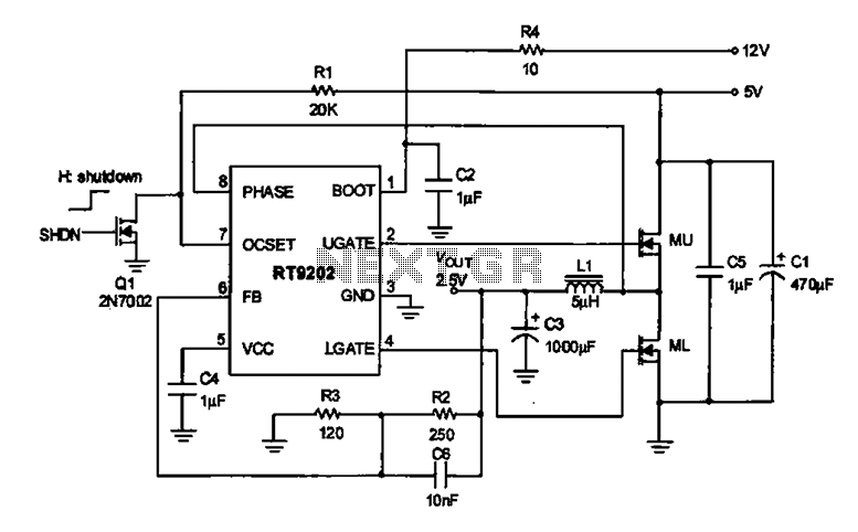
A 2.5V voltage regulator circuit is illustrated, which is part of a computer's motherboard. The circuit employs an oscillation circuit with the RT9202 control core chip, converting a 5V input supply into a regulated +2.5V output voltage, with the...
Warning: include(partials/cookie-banner.php): Failed to open stream: Permission denied in /var/www/html/nextgr/view-circuit.php on line 713
Warning: include(): Failed opening 'partials/cookie-banner.php' for inclusion (include_path='.:/usr/share/php') in /var/www/html/nextgr/view-circuit.php on line 713