
voltage inverter
The circuit described utilizes a NE555 timer IC configured to function as an inverter, effectively reversing the polarity of the input signal. The output current capability is limited to 200mA, making it suitable for low-power applications.
The NE555 timer (U1) is a versatile integrated circuit capable of operating in various modes. In this configuration, it is likely set up in an astable or monostable mode, depending on the desired output characteristics. The timing components, including resistors R1, R2, and R3, play a crucial role in determining the frequency and duty cycle of the output waveform.
R1 is a 1.2k ohm resistor, R2 is a 3.9k ohm resistor, and R3 is a 1k ohm resistor. These resistors are selected with a tolerance of 5 or 10 percent and rated for 1/4-watt power dissipation, ensuring stable operation under typical conditions. The resistor values can be adjusted to modify the timing characteristics of the NE555, thus influencing the inverter's performance.
C1, a 0.05 uF ceramic capacitor, is likely used for timing purposes, while C2 and C3 are larger 220 uF electrolytic capacitors, which may serve as decoupling capacitors to stabilize the power supply and filter out noise from the circuit. The use of electrolytic capacitors with a tolerance of 10 percent ensures reliable operation and maintains the integrity of the output signal.
Diodes D1 and D2 are 1N4002 diodes, which provide protection against reverse polarity and prevent damage to the circuit components. These diodes are essential in ensuring that the inverter operates correctly by allowing current to flow in one direction while blocking reverse current.
Overall, this inverter circuit is designed for simplicity and efficiency, making it a practical choice for applications requiring inverted signal polarity with limited current output. Proper attention to component selection and circuit layout will enhance the reliability and performance of the design.This circuit inverts the polarity of the input. output is limited to less that 200mA. U1 NE555 timer IC R1 1.2k ohm resistor R2 3.9k ohm resistor R3 1k ohm resistor C1 0.05 uF ceramic capacitor C2, C3 220 uF electrolytic capacitor D1, D2 1N4002 diode all resistors are 5 or 10 percent tolerance, 1/4-watt all capacitors are 10 perc 🔗 External reference
Related Circuits
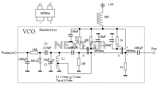
The VCO is based on a Hartley oscillator. The frequency is determined by L1 and capacitor C1. The tuning voltage will change the capacitance in the varactor BB132 which will change the oscillation frequency. The value of capacitor C2...
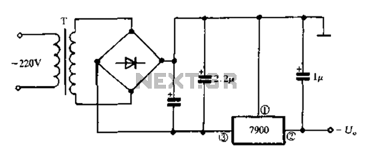
7900 series three-terminal fixed negative output voltage regulator circuit The 7900 series comprises a range of three-terminal fixed negative voltage regulators designed to provide stable output voltages. These regulators are specifically engineered to deliver a consistent output voltage, which is...
This DC voltage doubler circuit generates a voltage that is double its supply voltage. It is beneficial when a higher voltage level is required from a single power source. The DC voltage doubler circuit typically employs a combination of capacitors...

A project is underway that necessitates the conversion of a 0-10V DC supply into a linear frequency range in the form of a square wave. The project involves designing a circuit that takes a direct current (DC) voltage input ranging...

This device is designed to be a simple, inexpensive comparator intended for use in a solar cell power supply setup where a quick "too low" or "just right" voltage indicator is needed. The circuit consists of one 5V regulator,...
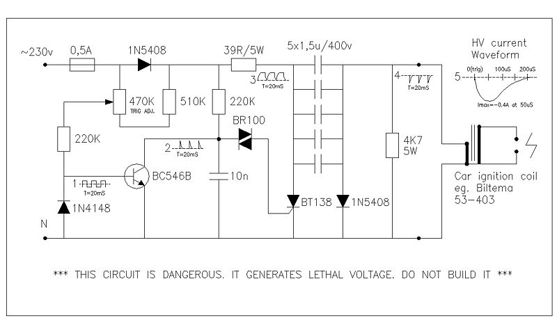
This circuit generates high voltage pulses from a 230 VAC line voltage. The drive end's swing comparator circuit was developed by the creator of this page. The working end is derived from a stroboscope trigger supply circuit. All circuits...